The three OPTs I've tried have been E-I cores so I can't speak for advantages/disadvantages of other core types. I can't imagine there'd be a big difference between an E-I core and a C core. Between E-I/C cores and a toroid, I would imagine more potential for differences. But that's a guess.
In the end, I would think that the technique used in winding the transformer has far more impact on the sound that the choice of core shape. By technique, I mean the layering of the different windings, interleaving, multiple strands in parallel, etc. But again, that's a guess.
I leave the winding of OPTs to the pros.
~Tom
Funny you should ask. I just started on the metalwork for the chassis today. I completed the plans over Christmas so this is not exactly a fast process... But I decided to take this week off from work so I could get some headway on this project. The circuit description of the 300B amp is also slowly taking shape on my website.
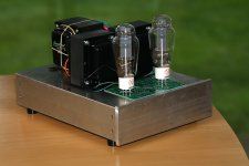
The amp is still sitting in "DeathTrap" mode in my living room. Playing Dire Straits right now... /me like.
~Tom
The amp is still sitting in "DeathTrap" mode in my living room. Playing Dire Straits right now... /me like.
~Tom
The chassis is coming together. As attached image shows, it's work in progress. But you get the general idea. The chassis measures approx. 11x15 inches. The sides are 3" tall, 1/8" thick architectural aluminum channel, the top plate is 1/8" aluminum sheet, and the front 3/8" extruded aluminum rectangle bar stock. I could probably have used thinner materials, but I like having enough material thickness to be able to cut threads so I went with 1/8" thick aluminum.
The type and position of the feet is not finalized. I would prefer them to be less visible.
~Tom
The type and position of the feet is not finalized. I would prefer them to be less visible.
~Tom
Attachments
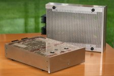
That looks more like a CNC job than hand drilling.
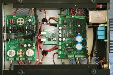
It is amazingly compact thanks to the unusually small regulators. Having the heat sink out back will also help things stay cooler than they otherwise would.
This amp will have such a crazy size/weight mismatch. Anybody who lifts it up will surely think that they are lifting a block of steel or lead.
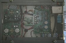
Thanks! No CNC here. The bottom plate is perforated sheet. The 546 vent holes (per chassis) on the top plate were drilled by hand (using a drill press, obviously). As were all the other holes. I used a stepped drill for the big holes.
For the vent holes, I made a jig from a piece of perf plate and a scrap piece of plywood. The perforated plate was used as a drill template. I held the perf plate, top plate, and plywood together with three brass pins. It worked like a charm and turned out really good.
~Tom
For the vent holes, I made a jig from a piece of perf plate and a scrap piece of plywood. The perforated plate was used as a drill template. I held the perf plate, top plate, and plywood together with three brass pins. It worked like a charm and turned out really good.
~Tom
Last edited:
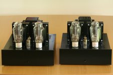
Twins...
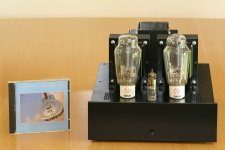
This project is finally drawing to a close. I've enjoyed the ride, but am glad to finally see the fruits of my hard work and allow this project to enter "maintenance mode".
I'm really pleased with the results. The sound quality of this amp is quite remarkable. I'm finding new detail in recordings I thought I knew inside and out. But the biggest surprise has been the sound stage. The imaging, width, and depth of the sound stage is unlike anything I've experienced before. I really like it.
I started this project over three years ago and it has spun off two side projects; the 21st Century Maida Regulator and Universal Filament Regulator.
The final amplifier uses three of my circuits:
- 21st Century Maida Regulator for B+ regulation
- 3x Universal Filament Regulator (stacked, 15 mm between boards in the center of the chassis)
- 300B Driver Board
I ended up using JJ 300B tubes and 6N6P drivers. I'm getting about 0.2 % THD (1 kHz, 1 W) and 10 W (3 % THD, 1 kHz). I'll follow up with more measurements at a later date.
Dimensions & weight: Approx. 30 x 40 x 25 cm (W x D x H). 17.3 kg.
For future reference, here are the relevant DIY Audio threads leading up to this design:
http://www.diyaudio.com/forums/tubes-valves/164390-rfc-300b-driven-anode-follower-6j5-6sn7.html
http://www.diyaudio.com/forums/tubes-valves/207968-300b-other-dht-biasing-options.html
~Tom
Attachments
-
 300B_Amps_Front_1000x1500.jpg358.2 KB · Views: 968
 -
 300B_Amps_Rear_1000x1500.jpg338.1 KB · Views: 937
 -
 300B_Amp_Bottom_1000x1500.jpg386.6 KB · Views: 826
 -
 300B_Amp_Open_1000x1500.jpg831.1 KB · Views: 504
 -
 300B_Amp_Front_CD_1000x1500.jpg343.2 KB · Views: 507
 -
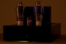 300B_Amp_Glow_1000x1500.jpg222.5 KB · Views: 372
Last edited:
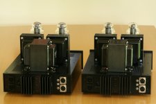
The toggle switches on the rear: The one in the middle is the ground lift. The other two are phase invert switches. They swap XLR pins 2 and 3. This is quite handy when you're using electronic crossovers and play with the filter order.
I used 4-pole speakON connectors for the output. Pair 1 is 4 ohm, pair 2 is 8 ohm.
~Tom
I used 4-pole speakON connectors for the output. Pair 1 is 4 ohm, pair 2 is 8 ohm.
~Tom
Check out the nanoDIGI for crossover duty. I have one and would not want to be without it ever again. It has a bit of a learning curve, mostly related to gain staging, but other than that it is the most cost effective, outright fun and flexible way to experiment. You will need as many DAC's as you have chassis in each speaker, because the nanoDIGI is S/PDIF in S/PDIF out, in other words all digital.
Last edited:
I've finally managed to collect my thoughts and learning experiences regarding my Damn Good 300B Amp and have updated my website to reflect this. Those who have bought the full set of boards may also be interested in the wiring diagram that shows how to connect it all together. Enjoy...
Neurochrome.com : : Audio : Damn Good 300B SET Amp
Also note that 'sceleratus' on Head-Fi is building one of these Damn Good 300B Amps to drive a pair of Audeze LCD2 headphones. He's taken lots of pictures during the build process. His thread is definitely worth checking out.
The Christiansen "DG" 300B Amplifier Build Thread
~Tom
E88CC/ECC88/6DJ8/6922 may be used as well
By making the following changes from the 6N6P configuration, the E88CC/ECC88/6DJ8/6922 tube may be used for driving the 300B as well.
R2 = R16 = 47 ohm
D5 = D10 = Short circuit (wire link)
It sounds pretty sweet to my ears with that driver tube.
~Tom
By making the following changes from the 6N6P configuration, the E88CC/ECC88/6DJ8/6922 tube may be used for driving the 300B as well.
R2 = R16 = 47 ohm
D5 = D10 = Short circuit (wire link)
It sounds pretty sweet to my ears with that driver tube.
~Tom
The ferrite bead I specified is not conductive. You can verify this with an ohmmeter. So it should not be an issue that it touches the drain lead of the MOSFET.
I had the same concern when I put mine together, actually. But after measuring the resistance of the ferrite, I concluded it wasn't an issue, and my two amps have been running fine since.
~Tom
I had the same concern when I put mine together, actually. But after measuring the resistance of the ferrite, I concluded it wasn't an issue, and my two amps have been running fine since.
~Tom
The Nickel-Zinc ferrites generally used in shield beads have high restivity. However, the Manganese-Zinc ferries used for power applications are conductive enough to cause trouble. It's a good thing to check and see which one you've got, as there are a few bead types made with the Mn-Zn material, and they all look superficially alike. I just checked a random E core from my desk detritus (Mn-Zn Philips 3F3 material) and measured about 56k resistance with a DVM. The resistivity is a non-linear function of applied voltage - I've had cores that accidentaly bridged line voltage AC turn red hot. At any rate, this is not an issue with Ni-Zn material.
Last edited:
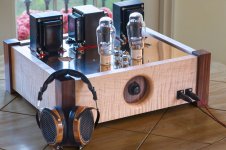
'Sceleratus' from Head-Fi.org was kind enough to share some pictures of his build. Polished bronze on burley maple with walnut corners. Bravely done! He's very pleased with the results of his efforts. He's using my 300B amp design to drive a pair of Audeze LCD2 magnetostat headphones.
~Tom
~Tom
Attachments
- Status
- This old topic is closed. If you want to reopen this topic, contact a moderator using the "Report Post" button.
- Home
- Vendor's Bazaar
- DeathTrap400™ : : A Pretty Damn Good 300B Amp