Getting back to Davorin's 6P41S tubes.
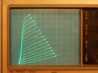
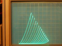
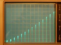
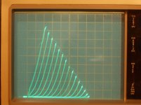
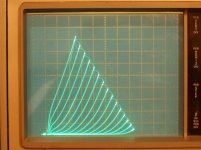
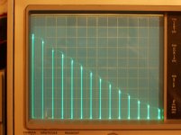
Here is the #67 6P41S tube in Crazy Drive with 0 to +170V drive, and then #67 in standard pentode mode with +170V on grid 2 and -2V steps on grid 1.
This was interesting, since the Ri are clearly different here. Other tubes have seemed more equal with the standard pentode Ri.
I'm also not seeing much boost (max current) with the Crazy drive here. Usually I see like 25% or so for the same max Vg2 due to +grid 1 assist.
I'll do the odd 6DQ5A soon, (essentially a 6JE6C I think) and see if this Ri difference holds up. Haven't traced Crazy drive in a while, but I think I set it up right. Would be interesting if I just found some new low output Ri variant, but probably not.
Both traces 50mA/div Vert. and 50V/div Horiz.
a) Crazy drive Rg2g1 19.6K Ohm, Rg1K 971 Ohm , +170/14 = +12.14V steps on g2
b) standard Pentode -2V steps on grid 1, +170V on grid 2
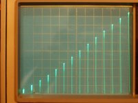
Attachments

Last edited:
could you do triode?
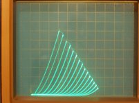
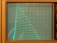
I did already. Here they are, 6P41S in triode:
50mA/div Vert., 50V/div Horiz.
a) tube #66 triode -5V steps
b) tube #67 triode -5V steps
c) a tube I had here earlier, triode -4V steps
Attachments
Looks like the 6P41S does have some kind of grid frames. The grid wires look aligned. I can't think of any reason that would make a difference. Grid 2 is directly driven by a voltage source, so any current difference there shouldn't be making any difference. I'll go back and retry Crazy drive on the 6P41S, maybe I'm losing my touch for adjusting the Rg2g1 and Rg1K adjustable pots. I can also do an Ip versus Vin plot to see if that is linear.
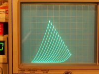
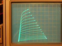
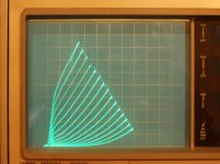
I went and re-checked the Crazy Drive setup and found that the 6P41S works best without Rg1k (or at least a high value like 25K). Rg2g1 was working well in the 7K to 10K Ohm range this way. The max current output was off the screen for 170V max drive, so I dropped that to 154V max drive for full screen seen below.
I did some linearity plots for Crazy Drive and also for g2 drive. Some improvement in linearity of Crazy versus g2 drive, but I couldn't get a straight ramping line using the usual 650 Ohm load in the tracer. I was able to get a straight line ramp with a higher load R, so 650 Ohm load is maybe too low for this tube.
Crazy drive is only needing 78% of the Vg2 drive to match the g2 only drive for max plate current. Safer for the grid 2 at least.
a) New Crazy Drive for 6P41S 50mA/div Vert, 50V/div Horiz. +11 V steps up to +154V
b) Linearity plot for Crazy Drive Ip versus Vg2 50mA/div Vert
c) Linearity plot for g2 drive Ip versus Vg2 50mA/div Vert.
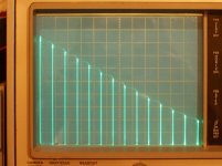
d) regular grid 1 pentode curves, 50ma/div Vert., 50V/div Horiz., -2V grid 1 steps, +170V on grid 2
The plate curves Ri is looking more comparable between Crazy Drive and regular pentode now.
It is interesting that I can get lower Ri with the previous Crazy Drive R setup (using higher Rg2g1), but the drive sensitivity was about the same as just g2 drive that way.
I did some linearity plots for Crazy Drive and also for g2 drive. Some improvement in linearity of Crazy versus g2 drive, but I couldn't get a straight ramping line using the usual 650 Ohm load in the tracer. I was able to get a straight line ramp with a higher load R, so 650 Ohm load is maybe too low for this tube.
Crazy drive is only needing 78% of the Vg2 drive to match the g2 only drive for max plate current. Safer for the grid 2 at least.
a) New Crazy Drive for 6P41S 50mA/div Vert, 50V/div Horiz. +11 V steps up to +154V
b) Linearity plot for Crazy Drive Ip versus Vg2 50mA/div Vert
c) Linearity plot for g2 drive Ip versus Vg2 50mA/div Vert.
d) regular grid 1 pentode curves, 50ma/div Vert., 50V/div Horiz., -2V grid 1 steps, +170V on grid 2
The plate curves Ri is looking more comparable between Crazy Drive and regular pentode now.
It is interesting that I can get lower Ri with the previous Crazy Drive R setup (using higher Rg2g1), but the drive sensitivity was about the same as just g2 drive that way.
Attachments
Last edited:
Here is a comparable linearity plot for the 6P41S in standard pentode, g1 drive, -2.7V steps, 170V on grid2
50 mA/div Vert.
( A Note on the previous Crazy drive curves above. To get the same max current as the conventional grid 1 drive with 170V on grid 2 (instead of full screen as plotted) only requires 133V max drive for grid 2 using Crazy Dive. So one can see the assist from +grid 1 in Crazy Drive lowers the max grid 2 V needed.)
Attachments

Last edited:
And now a comparable linearity plot for the 6P41S in internal native triode mode.
50mA/div Vert. 650 Ohm load line. Plot of Ip versus Vg1
Ri of the 6P41S triode would be approx. 250 Ohms at these currents.
Using a 3K Ohm load line it turned into a nearly flat ramp.
50mA/div Vert. 650 Ohm load line. Plot of Ip versus Vg1
Ri of the 6P41S triode would be approx. 250 Ohms at these currents.
Using a 3K Ohm load line it turned into a nearly flat ramp.
Attachments

Last edited:
Now for some UnSET/CED triode mode on the 6P41S.
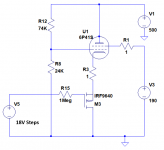
This was using 190V on grid 2, 18V steps on the cathode (input), 74K Ohm top R divider to grid 1, 24K Ohm bottom R divider to GND. (these R values are likely on the low side for practical use, but the ratio is what is important for setting the Mu.
50 mA/div Vert. 50V/div Horiz.
a) UnSet triode Curves, 18V steps
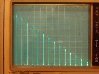
b) UnSET Linearity plot (Ip versus input V) 50 mA/div Vert., 18V steps (plot is flipped around from usual due to the NON inverting UnSET stage) 650 Ohm load line
c) Native triode Linearity plot (Ip versus input V) for internal triode, 650 Ohm load line -5V steps
d) Native triode curves -5V steps
You can see the better linearity of the UnSET versus the Native triode. (at 650 Ohm loadline on each) The residual distortion in the UnSET case is due to the actual curves being non straight diode lines, while the Native case is that plus the curve roll-over dist.
A higher Z load line will of course lower the distortion for either version. 650 Ohm loading makes the distortion comparison more obvious.
This was using 190V on grid 2, 18V steps on the cathode (input), 74K Ohm top R divider to grid 1, 24K Ohm bottom R divider to GND. (these R values are likely on the low side for practical use, but the ratio is what is important for setting the Mu.
50 mA/div Vert. 50V/div Horiz.
a) UnSet triode Curves, 18V steps
b) UnSET Linearity plot (Ip versus input V) 50 mA/div Vert., 18V steps (plot is flipped around from usual due to the NON inverting UnSET stage) 650 Ohm load line
c) Native triode Linearity plot (Ip versus input V) for internal triode, 650 Ohm load line -5V steps
d) Native triode curves -5V steps
You can see the better linearity of the UnSET versus the Native triode. (at 650 Ohm loadline on each) The residual distortion in the UnSET case is due to the actual curves being non straight diode lines, while the Native case is that plus the curve roll-over dist.
A higher Z load line will of course lower the distortion for either version. 650 Ohm loading makes the distortion comparison more obvious.
Attachments


Last edited:
Here is a comparable linearity plot...
I've read about your curve tracing hardware set-up. Can you briefly explain how you are doing your linearity plots please? Or point me to where you've explained it before?
Just wondering if my uTracer could be coaxed into doing them.
So the test set-up you're using is like this?
Yes, essentially.
The difference being that the TEK 576 can supply up to 2 Amps directly from the Step Amplifier on the BASE terminal (ie, DUT transistor base). So I just connect that (BASE connection ) to the tube cathode and adjust the OFFSET adjustment and voltage stepping to get the tube biasing and step range I want. (ie, Brute Force! Well, the TEK 576 weighs like 100 Lbs., it can do it )
There is a base current limit adjust knob, 20mA, 100mA, 500mA, 2A, (intended for low Beta transistors) so one can test what insufficient step current would do to the display curves. (they flat top at some plate current level typically)
The modified Step Amplifier I installed has 15 Amp MJL... transistors, so the actual limitation now is the Boost Supply I added for doing tube tracing. That supplies a little over 170V to the step amplifier, with some BIG caps in the Boost supply to hold it up. Realistically it can do a little over 250 mA average at 170V, so UnSET traces that do 0 to 500 mA sweeps just stay within bounds on average. Effectively, the bottom 15A PNP MJL1302A Step Amplifier transistor is acting as the P Mosfet in the standard UnSET diagram. The Step Amplifier also has a Neg. feedback from the output to make sure the output V is what it's supposed to be.
(Normally grid step current would be miniscule for tubes, but I had planned the Boost supply for doing stepped screen grid plots too, which draw some current. Fortuitously, I used a boost xfmr just big enough that could just handle this UnSet case too. Pure Luck!)
--------------------------------------------------------------
Can you briefly explain how you are doing your linearity plots please?
The TEK 576 has a setting on the Horizontal Scale Selector that can display the Step Generator V (actually the D/A converter V, -before- the gain controls in the Step Amplifier). The Vertical Scale selector is left at the vertical mA/div scale setting that was used for the normal plate curves.
So one gets plate current Vertically and step count Horizontally. With the 10 steps (11 traces) the TEK originally did, this probably positioned each bar at a graticule line. However, I modded the step counter logic to do 14 steps (15 traces) and the 15th bar no longer fits on the display. (probably some adjustment I could tweek to get that 15th trace squeezed in, have to look into that)
So the tops of the bars displayed this way are the max current reached in each normal plate curve on the right hand side where a load resistor limits the plate V (the sloping line on right side of normal plate curves) The TEK 576 has a 650 Ohm limit resistor for the 50 Watt max setting. So one is seeing current bars corresponding to a 650 Ohm load line. (like a 2600 OHM P-P OT)
There is a Variac knob in front (left side) for adjusting the max voltage put out by the 60 Hz plate V transformer during tracing. This allows one to change the position of the load line horizontally (in normal curve displays), effectively giving one a "bias" control for setting the horiz. load line position for linearity testing.
The different max Watt scales selectable on the 576 do provide different load limit resistors, but these are too coarse a selection to be usable for observing different load lines for a given tube. I have installed some switches and power resistors inside the 576 to shunt the load resistor down by smaller increments, but I need to make a similar set of adjustments for series up incrementing the load resistor too. (even more so needed, it appears) Then one could see how linearity acts versus different load R.
----
No doubt the software in the uTracer or others could be modded to do a similar linearity test. Mod wise, I guess one would just provide a switch to select plate V (as usual) or step V (usually grid V) for the horizontal display.
If there is a D/A in the design, tapping that might give you fixed step voltages to display horizontally, which is convenient if one is adjusting other parameters while watching the results. However, with modern 12 bit or more D/A chips available, the -full- scaling of the V steps may be being done in the D/A already, so you won't be able to get a fixed horizontal display without an attenuator to keep that width steady. The TEK 576 just has a 4 bit D/A driven by a 4 bit TTL counter, then the V scaling is done after it in the step amplifier.
--------------------------------
Well, the Mu factor I used above for the 6P41S UnSET was pretty low, so I think I'll try to get a higher Mu UnSET curve trace next. Then on to some curves for the odd 6DQ5A tubes.
Last edited:
Although the µTracer 3 only swing negative grid values, "displacing" the ground from schematic to a eg. -25Vdc (including drain and UnSET setting resistors) make possible to use the negative swing from µTracer, if I not miss something.
The µTracer operates in pulsed mode, but then the MOSFET/tube combination will be a lot faster than the tracer pulses") so no problem here
so no problem here
The µTracer operates in pulsed mode, but then the MOSFET/tube combination will be a lot faster than the tracer pulses
so no problem hereNo doubt the software in the uTracer or others could be modded to do a similar linearity test.
I built a set-up to do crazy-drive curve tracing. I could build another to do UNSET curve tracing. I'll add it to my project list.
Then the uTracer "I(Vg, Va) with Vs, Vh constant" measurement type should produce a linearity plot.
Attachments
OOPs, correction to the step V for the UnSET case in post 1491.
should be 9V steps for those
14 steps of 18V would be beyond the max 170V the step supply can do!
I left out a factor of 2 in scaling when I calc'd that earlier. That now fits with the UnSET tube Mu being approx. 3 then, fitting the Fdbk resistors ratio (74K/24K).
UnSet triode Curves, 18V steps
UnSET Linearity plot (Ip versus input V) 50 mA/div Vert., 18V steps
should be 9V steps for those
14 steps of 18V would be beyond the max 170V the step supply can do!
I left out a factor of 2 in scaling when I calc'd that earlier. That now fits with the UnSET tube Mu being approx. 3 then, fitting the Fdbk resistors ratio (74K/24K).
Last edited:
Some more 6P41S in UnSET mode at higher Mu programming.
1st set with 180K and 30K resistors, 4V steps, 190V on grid 2
approx. Mu 6 expected, looks like I got Mu 8.7
2nd set with 180K and 15K resistors, 2.5V steps, 190V on grid 2
approx. Mu 12 expected, looks like I got Mu 17.5
All 50 mA/div Vert., 50V/div Horiz. (for plate curves)
a) UnSET 6P41S Curves 180K, 30K, 4V steps, 190V grid 2
b) UnSet 6P41S Linearity 180K, 30K, 4V steps, 190V grid 2
c) UnSET 6P41S Curves 180K, 15K, 2.5V steps, 190V grid 2
d) UnSET 6P41S Linearity 180K, 15K, 2.5V steps, 190V grid 2
Looks like one can reduce grid 2 V at higher Mu factors. 170V works OK for the last set here.
The earlier Mu 3 UnSET curves, above, needed 190V on grid 2, or else it started to flat top.
Going above 200K for the plate to grid 1 resistor produced some instability of strange sort, was getting twinned up curve spacings vertically. No doubt related to sweeping the plate V in a different direction for every other curve. (0 to 350V versus 350V to 0 etc)
Hmm, the last set of curves here I should have adjusted the offset (bias) to lower the current more. The curves get a bit more closer together at the lower currents than the 1st case here. As one would expect, setting up for a higher Mu factor puts less N Fdbk into the triode operation, so linearity will get worse.
Attachments
Last edited:
- Home
- Amplifiers
- Tubes / Valves
- Those Magnificent Television Tubes