How about PP2C? Designed by the late Allen Wright. He used to mail (the schematic) it to everyone who asked him for it.
Or the PP1C which uses EL34. Later on Allen added as CCS in the output stages as well. Apperently with positive results.
I second the PP2C suggestion. It should be one of the best sounding power amps.
Hi all,
I've been given the makings of an EL34 PP amp - chassis, valves, iron etc. But I'd like to try a different driver stage. I've got about 500V of B+ to play with, good current capability and enough heater current to run the 4 EL34s, 2 x 12..7 and 600-800 mA of 6.3V heaters. Although I do have other Tx I could add in if more current is needed for heaters.
Could someone point me in the direction of a good sounding EL34 PP amp? Something with 6SN7, 6N2P or the 12..7 series would be an added bonus!!
I would run the EL34s as pentodes with a regulated G2.
Then use an SRPP with 6N2P triodes to drive them.
Then the amplifier feedback loop just goes straight from the EL34 anode to the bottom SRPP cathode. Make it a lot of feedback, and make this the only feedback. Bias the SRPP with 1k resistors, not sure what the bias for the EL34s would be in pentode mode (so check datasheet curves) but I'd allow for adjustment around -70V as a guess.
Then use a low impedance input tube like an ECC88, without feedback.
John,
I know you already have a Baby Huey but if desired you can do an EL34 BH. 6N2p or 12AX7 + 2 x EL34 per channel. Give me a PM if you want to go this way.
Cheers,
Ian
I know you already have a Baby Huey but if desired you can do an EL34 BH. 6N2p or 12AX7 + 2 x EL34 per channel. Give me a PM if you want to go this way.
Cheers,
Ian
Hello woodturner-fran,
Take a look on http://crude.axing.se/ at the HFTA link Jax made this amplifier as a contribution to hifiroum.nu. This amplifier is built of several members which all the praise its ability to sound good.
I myself collecting components to build an HFTA allmost all iron is Hammond, the OPT where I have chosen Edcors CXPP60-8-6.6K after I had heard the amp in another audio friends home the opportunity to use the KT88 by changing the bias make it more all-round.
Here is the link where it is discussed HiFiForum.nu - HFTA (HifiForum Tube Amplifier) unfortunately is in Swedish.
Anders
Thanks for those links, Anders.
(I spent the past hour reading....)
Looks like a good (nice and complex) project that's been fine-tuned via sims and also building some operating units. (not always the case with web 'projects').
Chrome does a reasonable job translating the Swedish; it is not too difficult to 'fill in the blanks' in most cases.
A couple of comments for other non-Swedish viewers:
There are a few spots where 6.3 volts appears on my monitor screen as 63v.
Also, HT apparently means 'Speaker connection' in Swedish, not the more common (Brit?) meaning of 'High Tension' aka HV. Not that anybody reading would make that mistake for long!
Woodturner Fran...any updates?
I have begun the collection of parts for the tubecad circuit.
Iron is ordered - edcor
tubes on the way - NOS6sn7's and new JJ EL34L's
Ordered some K40Y-9's from ebay - 8pcs 630V 0.22uF
The PSU is a modified tubecad PS-3 with 500V electrolytics and 630V film
I still need a chassis - thinking this may go into a hifi200 4U case
A 12.6V Xformer for the EL34 heaters - wired in series
Still debating CCS for the EL34 bias
LED for the front 6sn7 cathode
Nothing yet - building a set of frugal horns and repairing a 211 set amp got in the way! I hope to get back at it next week.
Looks like you have a good plan though....
Looks like you have a good plan though....
Making progress on the Tubecad schematic...with a couple tweaks in mind.
1. CCS on the EL34's using an LM317HV - good to like 57volts
2. Red LED on the cathode of the input 6SN7
Iron:
Edcor XPWR155 120
Edcor CXPP60-MS-6.6K
Triad C-14X PSU choke
Tubecad PS-3 PSU (500V electrolytics/630V Film)
Hammond 12.6V CT for the EL34 heaters - series wired
NOS 6SN7GT's
JJ EL34L's "new"
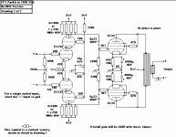
If you have UL taps, you should consider using Douglas Picard's E-Linear circuit. He's posted it a number of times but of course I can't put my hands on it right now. The version I built uses a pair of 6AC7 pentodes for the input/driver stage. It's one of the best sounding amps I've ever heard.
Here's the E-Linear circuit. Look at Post #4.
http://www.diyaudio.com/forums/tube...-build-25-30-wpc-push-pull-amp-need-help.html
http://www.diyaudio.com/forums/tube...-build-25-30-wpc-push-pull-amp-need-help.html
Nice work!!
Mine has stalled because I discovered one of my OPTs was damaged.... very low output on that side.
Fran
Mine has stalled because I discovered one of my OPTs was damaged.... very low output on that side.
Fran
well I ran into a little snag. The russian K40y9s are too large for the socket layout I have...UGH!!!
So, my 2 options are to:
1. Get smaller caps - this would be $$$ - thinking auricaps but that would be like $90
2. I am toying around with a PCB layout that would enable me to use the russian caps - just need some PCB octal sockets and another copper board...I will post my layout when I have it debugged...
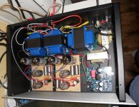
Some progress...I have decided to give some homemade single sided PCB's a try. Attached is a full PDF with silk and copper layers.
I will have to run a little extra wire for the heaters. I also plan to use a balance pot on the CCS cathode circuit. I plan to have all resistors on the bottom/copper trace side and the coupling caps and sockets on topside. Still need to think about taking certain measurements without having to dismount the boards from the chassis...Might need to break out the sharpie before I etch!
I will have to run a little extra wire for the heaters. I also plan to use a balance pot on the CCS cathode circuit. I plan to have all resistors on the bottom/copper trace side and the coupling caps and sockets on topside. Still need to think about taking certain measurements without having to dismount the boards from the chassis...Might need to break out the sharpie before I etch!
Attachments
So the pcbs look like they will work nicely...I have made one and stuffed the sockets and the russian caps.


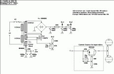
Well, I discovered an error with the cathode CCS, fixed now - not on my schematic yet though...
Got one channel up and running!!! Raw B+ was 510V. With the tubes in one channel it is running at 460V. The CCS is running about 50mA per tube so I may increase the ADJ resistor a bit...My PT is rated at 200mA...so I would like to get the power section down to about 180mA at most.
The next PCB is etching as I type....
The amp lives!!! I need to tidy up some of the OPT wiring and maybe implement the feedback section...running no feedback at all now either on input and output.
Did the CCS on the EL34 cathodes running 48mA each tube
Did the red LED on the front input tube cathode B+ is 405...and this amp is dead silent...
One thing though is that there is a loud buzz audible from the 12.6V hammond EL34 filament xformer. The signal is totally silent but you can hear the xformer if you get near the amp...fudge...
This is a really nifty amp...I will post pics as soon as my digicam battery recharges...
1K resistor at pin 5 of power tube
Hi,
This looks nice congrats!
The only thing that you should change is the 1K res. at the right tube on the PCB has to be as close as possible to the tube socket as possible like the left one. I can not find the schematic of your amp but the layout of the PCB shows a long line via the 1K res. to the power tube.
Just my tow cents. It's a bit late I know but it can be done without to much modifications.
Regards,
Audiofanatic 😉
- Status
- Not open for further replies.
- Home
- Amplifiers
- Tubes / Valves
- A good sounding EL34 PP sch please