I am doing my experiments and I want low output impedance. I was thinking of using the 6j52p for this.
DHTs like 26 sound much better in a preamp. You could use something like a LL1660 in step-down if you want a low output impedance, like if you have a solid state amp.
6J52P in a preamp? Why? it's not a DHT, not a triode and has far too much gain. That's a tube that could be a driver for a 300b in a 2 stage tube amp for instance.
> 3. What is R1 on Rod's board?
for 2P29L, please use R1 = 8.2Ω 1W+ and wirewound only.
The low current means high resistance for the filament. It makes for more sensitivity to noise pickup. The DHT should be away from any chokes or transformers. Screened cable from Raw DC to the regulator is helpful (use twin-ax: audio patch cable, or Mic cable).
I am doing my experiments and I want low output impedance. I was thinking of using the 6j52p for this.
For low output impedance there's the Bartola source follower,
Ale uses it in his preamp designs.


I tried my 6p21s prototype preamp on my technics su 8600. I strongly advise against using a switching power supply to power the filaments and polarize the tube, it is noisy and well audible. So I replaced it with a transformer and a regulator and since then there is no longer the slightest hum. My listening impressions are good, the bass are very present.
Otherwise the 6p21s is a pretty microphonic tube, when I tap the floor it can be heard through the speaker.
 [/url][/IMG]
Otherwise the 6p21s is a pretty microphonic tube, when I tap the floor it can be heard through the speaker.
Well done, although in the past I read 6P21S are very low service time tubes, something like 500 hours. This discouraged me to try this stash of tubes.
I have 6 new 6P21S for sale cheap. Tried a couple briefly as outputs and never got them to sound good so I abandoned the idea.
I read it too: filaments failure.Well done, although in the past I read 6P21S are very low service time tubes, something like 500 hours. This discouraged me to try this stash of tubes.
But :
at first ,this tube is cheap.
Less than 10€ for 500 hours.
How does it go for a 300b?(ok, the sound is not the same...)
Second ,how was used the tube ?
I read it too: filaments failure.
But :
at first ,this tube is cheap.
Less than 10€ for 500 hours.
How does it go for a 300b?(ok, the sound is not the same...)
Second ,how was used the tube ?
The tube is not remotely comparable to a 300b which is a wonderful tube even in its cheaper versions. It's not even comparable to a 6C4C or a 4P1L. Russian audiophiles would have jumped on this tube if it was really good, but it isn't so they haven't. I used it in a SE amp at pretty much the recommended operating point. It lasted about 30 minutes as an experiment.
I have been working on a 4P1L project over the past year and a half. I have Rod's regulators and raw supply kit and Ale's gyrator boards.
I am at the stage where I've assembled the raw supply, along with the regulators and ready to test but I would like to get some suggestions on how to proceed and what my first attempt at using PSUD to model the supply looks like.
Using Rod's supply kit with a Hammond 266L24, Wurth ATPG caps, 159ZC as L1 in lieu of R2, a 0.82 R3. When building the model I don't know how to account for having the second dropping resistor on the bottom. I set it to that because it measured similar to the DCR of the choke. I do not know the ESR of the Wurth caps. I measured the parallel connected primary and secondary on the power transformer.
Here is a look at the results I got.

Built up and unloaded I am getting about 18VDC at the raw supply output.
This voltage needs some context and leads me to my next questions.
What is the recommended headroom for Rod's v8 regulator?
How should I bias my 4P1L and what is a good operating point based on people's experience with Ale's Siberian designs and the gyrator circuit over the years? I have built up my chassis to accommodate 12 SiC diodes mounted along an aluminum bar for 6 on each tube.
Should I feed 13V to 15V into the regulator and go with SiC filament bias? At 550-650mA is the Cree C3D02060 going to actually give me a full 6V of voltage drop? Using the vtadiy.com loadline calculator that would put me around 139V on the anode and running 32mA through the tube? What about adding a few ohms below the diode string to increase the bias to 7-8V. I lieu of SiC filament bias altogether I also have the correct size Russian wire wound resistors to use in the filament instead. Just wondering where is a good starting point for what I have.
Or do I ignore filament bias altogether, remodel and rebuild the raw supply for 7V and use the SiC arrangement in cathode bias. What about the significantly lower current through the diodes? Will they not drop enough voltage and force me to lower the anode too much? For the 4P1L in line stage use is there any reason not to run it above 35mA or even closer to 40ma?
I am at the stage where I've assembled the raw supply, along with the regulators and ready to test but I would like to get some suggestions on how to proceed and what my first attempt at using PSUD to model the supply looks like.
Using Rod's supply kit with a Hammond 266L24, Wurth ATPG caps, 159ZC as L1 in lieu of R2, a 0.82 R3. When building the model I don't know how to account for having the second dropping resistor on the bottom. I set it to that because it measured similar to the DCR of the choke. I do not know the ESR of the Wurth caps. I measured the parallel connected primary and secondary on the power transformer.
Here is a look at the results I got.
Built up and unloaded I am getting about 18VDC at the raw supply output.
This voltage needs some context and leads me to my next questions.
What is the recommended headroom for Rod's v8 regulator?
How should I bias my 4P1L and what is a good operating point based on people's experience with Ale's Siberian designs and the gyrator circuit over the years? I have built up my chassis to accommodate 12 SiC diodes mounted along an aluminum bar for 6 on each tube.
Should I feed 13V to 15V into the regulator and go with SiC filament bias? At 550-650mA is the Cree C3D02060 going to actually give me a full 6V of voltage drop? Using the vtadiy.com loadline calculator that would put me around 139V on the anode and running 32mA through the tube? What about adding a few ohms below the diode string to increase the bias to 7-8V. I lieu of SiC filament bias altogether I also have the correct size Russian wire wound resistors to use in the filament instead. Just wondering where is a good starting point for what I have.
Or do I ignore filament bias altogether, remodel and rebuild the raw supply for 7V and use the SiC arrangement in cathode bias. What about the significantly lower current through the diodes? Will they not drop enough voltage and force me to lower the anode too much? For the 4P1L in line stage use is there any reason not to run it above 35mA or even closer to 40ma?
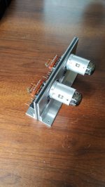
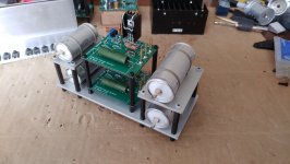
Here are some pictures of the boards and chassis I built to mount the tubes, diodes and grid resistors. I assembled what I call the gyrator tower to fit the FT-3 bypass and output caps. Also seen are Ale's cap multiplier boards in lieu of a HT reg. On hand are the new Bartola HT supply PCB which are having parts sourced and also something I may have questions about when it comes time to model.
I've yet to decide on how I want to implement a volume control. My plan for this preamp was to use its full 19dB of gain in conjunction with an F4 (convert my Aleph J) or some yet to be released SIT high power follower amp from Nelson or Zen Mod.

I've yet to decide on how I want to implement a volume control. My plan for this preamp was to use its full 19dB of gain in conjunction with an F4 (convert my Aleph J) or some yet to be released SIT high power follower amp from Nelson or Zen Mod.
Attachments
The tube is not remotely comparable to a 300b which is a wonderful tube even in its cheaper versions. It's not even comparable to a 6C4C or a 4P1L. Russian audiophiles would have jumped on this tube if it was really good, but it isn't so they haven't. I used it in a SE amp at pretty much the recommended operating point. It lasted about 30 minutes as an experiment.
Andy;
Russian audiophiles actually enjoy 4P1L tubes. I mean, those who prefer quality over the hype. However, thanks to USSR where "You pretend to pay, we pretend to work", people still believe that everything foreign is better than made in USSR. It was true, except made for military components.
Yes, since it was a military tube, nobody wanted to go to jail if it serves less than guaranteed. But 6P21S was hyped because it is a directly heated tube. It's linearity and tolerance is far from 4P1L. You can see many old threads about 6P21S on Russian forums, they were tried in all positions possible, nothing good.Datasheet gives 500 hours.
Jason:
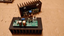
The assembly work looks good. What's the little heatsink?
Notes on the filament regulator Raw DC:
I prefer resistor filament bias, but you can easily try the diodes filament biased - just add of subtract diodes to get the approximately correct voltage.
The assembly work looks good. What's the little heatsink?
Notes on the filament regulator Raw DC:
- aim for input voltage 4V above the output;
- PSUD2 value for ESR of 10mF capacitor is about 50m Ohm.
- to account for the dropper resistor in the negative side, simply add the value to the positive side resistor (or the ESR of the choke);
- PSUD2 will give a reasonable estimate for the power transformer if you double click on it, then hit the ... button and put the voltage and current rating in. Use 12% for the regulation value. It then gives you an open circuit voltage and ESR...
I prefer resistor filament bias, but you can easily try the diodes filament biased - just add of subtract diodes to get the approximately correct voltage.
- Home
- Amplifiers
- Tubes / Valves
- 4P1L DHT Line Stage