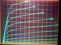
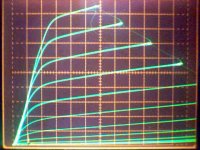
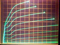
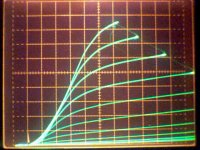
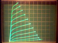
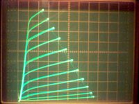
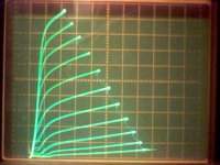
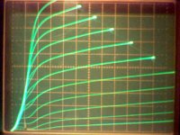
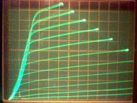
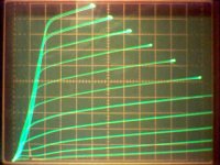
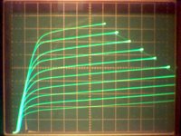
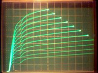
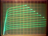
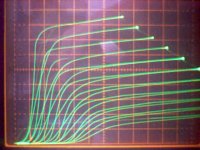
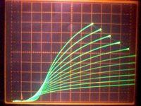
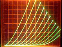
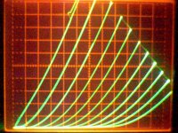
Here are some curves for 6HB6 with g3 voltages altered.
For all: 20 V/div horiz., 10 mA/div vert., 100 V on g2, 0.53 V steps on g1
Except: 50 V/div horiz. on Plots 6,7,8
Plot1 thru 5 are for true pentode version of 6HB6.
Plot6,7,8 are for beam pentode version of 6HB6
Plot1: 0 V on g3
Plot2: -30 V on g3
Plot3: +30 V on g3
Plot4: no connection to g3
Plot5: -140 V on g3
Plot6: 0 V on g3
Plot7: -30 V on g3
Plot8: +30 V on g3
Attachments
Last edited:
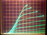
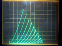
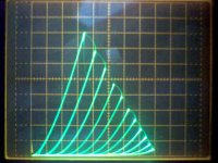
Here are some curves for 29GK6 (very similar to EL84/6BQ5), with altered g3 voltages.
All plots 20V/div horiz., 10 mA/div vert., 0.53 V steps on g1, 100 V on g2
Plots 1,2,3 are for g3 at 0 V.
I noticed a strange phenomena here. Notice the doubled versions of each trace. I posted 3 snapshots because the camera catches varying numbers of retraces each time.
I had previously been ascribing this to 60 HZ ripple in the power supply of the curve tracer. The alternate curves are drawn on ascending and descending sides of the 60 Hz HV waveform. So it seemed likely that 60 Hz ripple somewhere was altering the results for leading and falling edges of the 60 Hz sine wave.
But here I had the 6HB6 on one socket and the 29GK6 on the other. A switch selects which one is connected to the tracer. There were NO doubled curves on the 6HB6 side, but doubled ones on the 29GK6 side. I tried re-seating all the wire connections to no avail. Final conclusion is that some tubes do not trace the same curve with ascending plate voltages versus descending plate voltages. Simply Shocking!!!!!
Plots 4,5 were set up to do 9 traces instead of the 10 trace curve sets previously. This locks the individual traces into always being on an ascending or descending side of the 60 Hz HV sine. (so no doubled up ones here ) Alternate traces still alternate between ascending and descending. Plot 4 differs from Plot 5 by getting the syncing with the 60 Hz flipped. Ie, what ascends in Plot 4 descends in Plot 5 and visa versa, consistantly. Verifying the hypothesis that the tube reacts differently to ascending and descending plate voltage.
This is shocking news. Some tubes have hysteresis effects!!
OK, back to g3 effects using 29GK6.
Plot 6 is with -30 V on g3
Plot 7 is with +30 V on g3
Disconnecting g3 had almost no effect with this tube.
Finally, Plot 8 is a 6BQ5/EL84 tube which has 0 V on g3 since it is internally connected to cathode.
No hysteresis evident here thankfully (audio).
Attachments
Last edited:
suppressor grid
here a mechanical comparison:
Comparison between 6BQ5 and chinese 6P15, both are true penthodes.
6BQ5 G2 is rates 2W, 300V
6P15 is rated 1.5W, max 200V
the tubes were opened:
spacings between the electrodes were found about to be the same.
Tests were performed with a micrometer, dimensions in mm:
6BQ5 6P15
G2 turns ~27 G2 turns ~ 35
G2 wire dia: 0.06 G2 wire dia: 0.06
G2 turns spacing: ~ 0.98 G2 turns spacing: 0.75
G3 turns: 10 G3 tuns: 21
G3 wire dia.: 0.1 G3 wire dia: 0.1
G3 turns spacing: 2.5 G3 turns spacing: 1.1
Cathode emission coating length in both tubes is ~ 25.5mm
in the 6P15 the suppressor grid has a bigger influence than in the 6BQ5
SF, December 2009
curves
as far as i remember, the "sharpening" effect of a slightly positive suppressor grid ( G3) voltage has been described in the radiotron tube handbook earlier, and it mentioned, that the plate voltage can swing to lower voltages.
as far as i remember, the "sharpening" effect of a slightly positive suppressor grid ( G3) voltage has been described in the radiotron tube handbook earlier, and it mentioned, that the plate voltage can swing to lower voltages.
Steve, I agree with your conclusions. With doubled up turns on the 6P15, it is likely to take only half the voltage on g3 to get the same effects as seen on 6BQ5 or alike. (could be larger non-linear scaling too)
On 6LE8, a positive voltage on g3 also reduces the g2 screen current. More electrons make it thru g3 to the plate when g3 is slightly positive. But, too much positive voltage on g3 will cause it to start absorbing electrons itself, heating g3.
One may not be able to conclude that positive g3 will always square up the curves though. I think it will depend on how effective the g3 was designed to be (# of turns). I have seen some tubes (one was plotted here earlier) where negative g3 squares up the curves, they apparently had an inneffective g3 design (grid wires too spaced out).
I found a data sheet for the 6P15, and it has rather rounded knees for curves. So it likely has an over effective g3. Positive V on g3 there will likely square it up. But keep in mind that squaring up the curves will change the sound of the tube, to more like a beam tube. I have seen some video tubes (6GN8 comes to mind) where I think they intentionally rounded the knees severely so as to remove 2nd Harmonic effects when operated in SE mode, which would be the usual mode for a video amp in a TV. For P-P mode, one probably would like the knees squared up, since 2nd harmonic cancels out anyway.
Last edited:
6p15
Dear smoking-amp,
you are totally right.
so far, i have connected the screen grid via 1K and a diode to supply of 150V DC. might be interesting to do the same with the G3. to change the sound is absolutely my intension, or even make it selectable during operation thru these measures. unfortunately, i dont have a curve tracer ( my old dream! ) to experiment a bit. there are only a few tubes mentioned from philips like the EF14 to have a positive G3. a negative G3 with the 6P15 causes interittend oscillation and not stable working.
its interesting, thatmost companies didnt say anything about G3 possibilities.
we have tons of that 6P15 here, selling cheap for about 1US$, so killing some, is not an issue. the built quality of this tube is even better than 6BQ5. most of the are dated from the 70s... early 80s made by Peking or Shuguang factory.
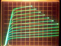
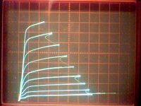
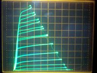
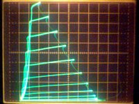
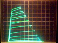
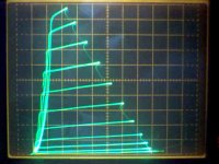
Couple of curve sets for two 29GK6s I found that go bonkers with g3 disconnected.
Notice the huge amount of hysteresis in the curves also with g3 discontected. Interestingly, these two tubes do not display hysteresis when g3 is set a 0 V.
Notice the huge amount of hysteresis in the curves also with g3 discontected. Interestingly, these two tubes do not display hysteresis when g3 is set a 0 V.
Attachments
Last edited:
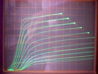
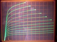
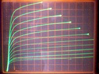
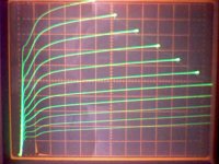
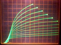
I tried out the other GU50 that Anatoliy sent, expecting it to show the same g3 effects as the 1st. No! Its different. +4 V on g3 squares up the curves optimally, whereas the other one squared up best at +14 V on g3. Here are some curves, and then the earlier GU50 at +14 V on g3.
Plot1: 0 V on g3
Plot2: +4 V on g3
Plot3: +15 V on g3
Plot4: +30 V on g3
Too much + V on g3 and it starts absorbing the plate current itself at low plate V.
Plot5: -4 V on g3
Plot 6: -15 V on g3
Plot7: -30 V on g3
Plot8: +14 V on g3 for the earlier GU50
Interestingly, the optimum squared up curves for the earlier GU50 (at +14 V)are more squared than the optimum for the later GU50 (at +4 V). I'm going to try the earlier GU50 again next at +4V on g3 to see if it at least matches the curves for the later one at +4 V.
Attachments

Last edited:
I tried out the other GU50 that Anatoliy sent, expecting it to show the same g3 effects as the 1st. No! Its different. +4 V on g3 squares up the curves optimally, whereas the other one squared up best at +14 V on g3. Here are some curves, and then the earlier GU50 at +14 V on g3.
Plot1: 0 V on g3
Plot2: +4 V on g3
Plot3: +15 V on g3
Plot4: +30 V on g3
Too much + V on g3 and it starts absorbing the plate current itself at low plate V.
Plot5: -4 V on g3
Plot 6: -15 V on g3
Plot7: -30 V on g3
Plot8: +14 V on g3 for the earlier GU50
Interestingly, the optimum squared up curves for the earlier GU50 (at +14 V)are more squared than the optimum for the later GU50 (at +4 V). I'm going to try the earlier GU50 again next at +4V on g3 to see if it at least matches the curves for the later one at +4 V.
Interesting. It's like zero to a little positive voltage puts g3 in the "right place" for beam tubes with nice sharp knees; a little more make it disappear, producing tetrode kinks and a super-steep diode line; and more still produces a pentode shape (aggressively attracting secondary electrons?). Maybe the different GU50s had different g3 spacing.
Mystery solved.
When I connect up both tubes with the same settings on the curve tracer, both act the same, with the same optimum +g3 too. What seems to effect the optimum level of +g3 is the bias setting on g1 and hence the operating current of the tube. g2 also affects the optimum +g3, although much more slowly. Looks like optimum g3 is tied directly to operating plate current.
The earlier GU50 curves were at a 10X higher current range on the curve tracer than the later set for the 2nd tube.
Peering through the slots of the GU50 plate, I see some curious alignments of grid wires. Looks like g1 and g2 have the same grid pitch, and might be aligned. g3 looks to have three wires for every 4 wires of g1 or g2. The LS50 datasheet indicates between 11 and 13 to 1 current ratio for plate current to g2 current. These probably are g1/g2 aligned.
Last edited:
Tube hysteresis effects:
At first I was thinking that a design flaw in the 29GK6 was responsible for the hysteresis effect which showed up in the 29GK6 I tested earlier in post 63. (Spangenberg does discuss some hysteretic knee design effects in tubes in his book) I found that I had two kinds of constructed 29GK6 tubes, so I sorted them out and started testing them on the tracer, expecting that I was going to be throwing out a bunch. But the construction does not seem to correlate well with the hysteresis effect.
From seeing the big effects on hysteresis caused by a disconnected g3, for some 29GK6s in post 68, I am thinking that the hysteresis I saw earlier is due to some uncontrolled charge in the tubes. This could be from gas absorbed on the surface of g3, like a mono-atomic layer, which acts as an insulator for charge to build up on. The immediate previous history of tube operation would determine how much charge is present. The charge would be acting like variation of the g3 voltage (and it only seems to take a few volts on g3 to make similar effects like the hysteresis effects seen).
It would be interesting to operate one of these hysteretic tubes for some time to see if the getter eventually cleans this problem up. Maybe this is what "tube break-in" is all about.
Or, possibly operate the tube with an excessive + voltage on g3 for a while, so as to heat g3 up enough to clear off any absorbed gas coating.
Last edited:
Did you check for oscillation?
The obvious explanation for open G3 is G3-P capacitance. That doesn't work so well when G3 is fixed.
Tim
The obvious explanation for open G3 is G3-P capacitance. That doesn't work so well when G3 is fixed.
Tim
"Did you check for oscillation?"
With g3 disconnected, I'm sure most of the effect is from plate to g3 capacitance. But notice that there are two different traces for each step, where normally only one should occur. By selecting the # of steps on the tracer, I can lock it in so that every other trace sweep is either increasing plate V or decreasing plate V consistantly. This then selects only one trace from the set for each step, with every other one looking somewhat similar (alternate traces are increasing or decreasing plate V from the power line). By flipping the traces # switch around some, I can get it to sync in on the other missing set. Ie, I have re-synced to opposite decreasing / increasing plate V traces. (Take a close look at plots 4 and 5 in post 63) I don't think HF oscillations would be smart enough to know that.
But in any case, the same thing happens with the "bad" hysteretic tubes, even with g3 connected to 0V, just better behaved with only the knees having the dual identities. (again, plots 1 thru 5 in post 63)
Last edited:
What I think is happening:
Having g3 disconnected, is most likely causing g3 to swing capacitively with plate voltage change, making g3 go + with increasing plate voltage and go - with decreasing plate voltage. This produces two widely different traces for each step, depending on whether plate voltage is going up or down for that step.
It was just this exaggerated magnification of the hysteresis problem that I saw earlier, that made me think that the hysteresis might be caused by some uncontrolled charge in the tube, like a dielectric film over the g3 (residual gas monolayer coating) allowing surface charge to vary despite g3 being bolted down to 0V.
Curiously though, some tubes I have tested do not seem to be bothered by a disconnected g3. They remain a mystery to me. But since Spangenberg mentions just such hysteretic variation around the knees, maybe it takes both problems together. A design that puts the tube hair trigger close to knee hysteresis, and a film coating on g3 to fire it off, greatly magnifying the effect.
Last edited:
"Can you plot screen current through these hysteresis curves?"
Not normally, the screen voltage comes from a set of external regulated supplies which I rigged into the tube selection switch to select them with the tube. But I could put a current probe on the wire and display that on a scope. Might be too weak a current to see though.
I was just getting started on trying that and put the tube back in the tracer, and .....! Hardly any hysteresis anymore. Don't know whats going on. But this hysteresis problem seems to show up every once and a while with some tube in it. So next time I see it, I'll try to look at the screen current. May still be some 60 Hz ripple problem in the tracer itself, but it only occured for one tube and not the other last night.
Hmmm, since there are two separate screen supplies, if only one of them developed ripple, it would have the same effect. I'll have to actually swap the tubes between sockets next time I see this.
Last edited:
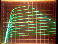
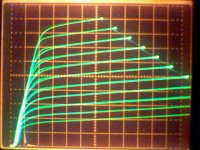
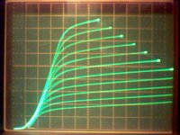
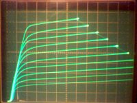
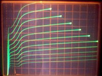
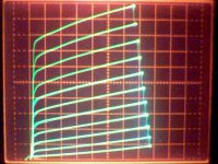
TheGimp sent a couple of 6P1Pev over, so here are some curves for them.
The 4400 and 3950 refer to gm numbers marked on the tubes.
Plot1: 4400 pent 50 V/div horiz., 10 mA/div vert., 100V on g2, 2.5 V steps g1
Plot2: 3950 pent 50 V/div horiz., 10 mA/div vert., 100V on g2, 2.5 V steps g1
Plot3: 4400 pent 50 V/div horiz., 10 mA/div vert., 106 V on g2, 2.5 V steps g1
Plot4: 3950 pent 50 V/div horiz., 10 mA/div vert., 87 V on g2 , 2.5 v steps g1
Plot5: 4400 triode 20 V/div horiz., 5 mA/div vert., 2.5 v steps g1
Plot6: 3950 triode 20 V/div horiz., 5 mA/div vert., 2.5 V steps g1
Plot7: 4400 triode 50 V/div horiz., 10 mA/div vert., 5 V steps g1
Plot8: 3950 triode 50 V/div horiz., 10 mA/div vert., 5 v steps g1
Plot9: 4400 pentode g2 drive 50 V/div horiz., 2 mA/div vert., 5.3 V steps g2
Attachments
-
 6P1P_4400.jpg29.9 KB · Views: 433
 -
 6P1P_3950_100Vg2.jpg39.8 KB · Views: 428
 -
 6P1P_4400_100Vg2.jpg40.7 KB · Views: 442
 -
 6P1P_3950.jpg27.3 KB · Views: 433
 -
 6P1P_4400_t.jpg46.2 KB · Views: 429
 -
 6P1P_3950_t.jpg46.3 KB · Views: 103
 -
 6P1P_T_4400.jpg27.9 KB · Views: 98
 -
 6P1P_T_3950.jpg28.7 KB · Views: 96
 -
 6P1P_g2drive.jpg37.2 KB · Views: 101
You will notice that the dreaded hysteresis problem has shown up again on plots 1 and 3 above. This time I tried swapping the tubes between socket positions on the tracer, and also tried swapping the screen supplies, and then both. In all cases the hysteresis problem followed the 4400 tube when in pentode mode. One difference I noted was that the 4400 tube draws less screen current for the same g2 voltage than the 3950 tube, 4 mA avg. DC versus 6 mA avg. DC.
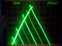
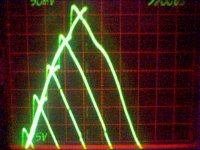
Per Tim's (Sch3mat1c) suggestion above, I tried getting a trace of the screen current drawn. This turned out to be rather difficult. The current probe could pick up the signal fine, but the camera could not capture traces that were 10 or 11 60 Hz cycles apart. What is needed is a storage scope and a variable hold-off trigger feature. I did manage to get a poor trace by turning the scope intensity up so that a dim residual trace shows up. These are sets of screen current curves sync'd to 60 Hz.
Trace set 1 is with the hysteretic tube, and trace set 2 is with the non hysteretic tube. Will be interesting to see if the problem clears up with time, like the earlier 29GK6 did.
Hmmm, well now that I see the pictures posted here, I can hardly make out the residual traces. Only one visible at all (and just barely) is the 2nd and 5th peaks down from top of the left picture. The pictures on my PC here are better apparently.
Attachments
Last edited:
- Home
- Amplifiers
- Tubes / Valves
- Suppresor Grid used for Feedback?