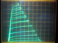
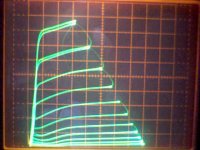
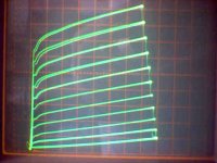
Did the amp have GNFB? This is the worst case of tube hysteresis I have seen yet in the tracer. I would think it would sound baaaad. But, as you can see from the curves, the problem shows up mainly at high power.
I just tried decreasing the filament voltage down to 3 V and then increasing it up to 10 V, but the hysteresis problem just stays put. The earlier problematic 29GK6 apparently cured itself after sitting cold on the bench for a few hours. Since g3 here is internally attached to the cathode, I can't try applying some positive voltage to g3 to heat that up.
Just tried a magnet on the tube. It sure messes up the curves while its near. But I couldn't make any change to the hysteresis problem, tube just goes back to the same when the magnet is removed.
Last edited:
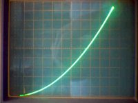
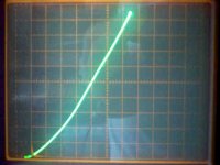
Well, been running that hysteretic tube for about an hour in the tracer. Here are before and after pictures. Seems to have improved a little. The apparent increase in hysteresis seen in the lower middle traces is just due to the camera shutter timing versus the tracer display timing (camera missed it in the earlier picture).
Attachments
Last edited:
I had about 6dB of GNFB at one point. Most of the time I ran it open loop.
The 4400 gm tube showed 4900gm when I first got it. It and the lower gm tube probably have ten hours of run time by now as I was using them as a worst case test in the prototype amp.
The 4400 gm tube showed 4900gm when I first got it. It and the lower gm tube probably have ten hours of run time by now as I was using them as a worst case test in the prototype amp.
Last edited:
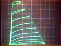
I have found a large clue to the mystery. The hysteresis affected curves begin near and above the g1 = 0 V level. I should have checked the biasing offset more carefully, (the 6P1P requires higher g2 voltages to avoid positive g1 curves than most of the tubes I have been testing). So you probably didn't run into this condition while testing in your amplifier. Here are some curves with g2 up at 183 V. The second set is with g1 forced to 0 V for reference (all else the same). Note the hysteresis begins near the 0 V g1 curve in the 1st set.
Still, mysterious why some tubes do the hysteresis thing and others don't. Also, no improvement in the 4400 tube overnight obviously. The g1 lead wires on the tester do not have stopper resistors on them, but do have a string of a dozen or so ferrite beads. The g2 lead wire has a 180 Ohm stopper and a string of ferrite beads. Both sides the same nominally. Swapping tubes around, the Hysteresis problem followed the tube and not the leads.
I'll run another set of pentode curves for both 6P1P tubes next with 0 V for g1 at the max curve.
Attachments
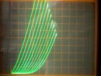
1st plot here is the same as the above plot, but with a 1K Ohm stopper resistor added to the g1 lead. Not much difference I would say. Scale for all plots are 50 V/div horiz., 10 mA/div vert., 2.5 V steps on g1. The 2nd and 3rd plots here are set up so that the top curve is for g1 at 0V.
Plot1: 4400 tube with 1 K stopper on g1, 183 V on g2, 2.5 V steps g1
Plot2: 4400 tube, 200V on g2, top curve at g1 = 0 V, 2.5 V steps g1
Plot3: 3950 tube, 200V on g2, top curve at g1 = 0 V, 2.5 V steps g1
PS:
I just tried the 1 K Ohm stopper plus beads on the g2 lead (instead of 180 Ohm before) of the 4400 tube and no obvious change, still same hysteresis.
Attachments

Last edited:
1st plot here is the same as the above plot, but with a 1K Ohm stopper resistor added to the g1 lead. Not much difference I would say. Scale for all plots are 50 V/div horiz., 10 mA/div vert., 2.5 V steps on g1. The 2nd and 3rd plots here are set up so that the top curve is for g1 at 0V.
Plot1: 4400 tube with 1 K stopper on g1, 183 V on g2, 2.5 V steps g1
Plot2: 4400 tube, 200V on g2, top curve at g1 = 0 V, 2.5 V steps g1
Plot3: 3950 tube, 200V on g2, top curve at g1 = 0 V, 2.5 V steps g1
PS:
I just tried the 1 K Ohm stopper plus beads on the g2 lead (instead of 180 Ohm before) of the 4400 tube and no obvious change, still same hysteresis.
Don,
Maybe some tubes are sourcing current from one of their electrodes into your drive circuit, causing a slope-dependent offset in some electrode voltage.
WAG
Michael
"Maybe some tubes are sourcing current from one of their electrodes into your drive circuit, causing a slope-dependent offset in some electrode voltage."
Well, the two screen grid supplies are linear regulated Xantrex XT250-0.25 rated for up to 0.25 Amp. They have a current limit control with an indicator LED for when current limiting occurs. Plus V and I digital readouts. I can artificially roll the current limit down till it limits and the top tube curves just get squashed. I've also tried swapping the screen supplies between the two tubes and no effect either.
The plate voltage and current are just passive pickoffs from the selected plate resistor to the scope deflection amplifiers. HV comes from a rectified but not filtered Xfmr. Even if the HV were getting dragged down, the display would just show that. Ie, the display shows what the tube is actually doing.
The g1 step generator output amplifier has been modified to a totem pole of MJL3281AG and MJL1302AG bipolars (on a heatsink), with MJE15032G and MJE15033G drivers, all in a feedback loop with an Op Amp (original Tektronix circuit, I just upgraded the transistors so it could handle a 200V or 15 Amp step range). This step generator would probably melt the lead wires before it gives up on the grid voltage (the tracer is after all intended for testing SS devices up to 220 watts).
There is a 1 Ohm current sense resistor in the step output with a selectable current limit circuit for 20 Ma, 100 mA or 500 mA. I have tried all these ranges and there is no effect on the tube curves. The current sense resistor is inside the voltage feedback loop.
The weak link would be the power supply for the step generator, still original Tek but with a temporary fix of 30 V added in series to get more step V range. But when I exceed the voltage supply available step-wise, it just stops at the max curve available.
I have also tried putting a 1 K Ohm stopper resistor in series with g1 or g2 leads, and no obvious effects were visible in the curves, so seems unlikely that any unusual grid currents are present.
Last edited:
The hysteresis effect on the tube curves is quite similar to what I have seen before when varying the g3 voltage. Ie, I could make one curve (rising Vp say) with a certain g3 voltage and the other curve (dropping Vp) with another g3 voltage. The 6P1P however has the g3 attached internally to the cathode. So no playing with that here. But my earlier suspicion of an effective dielectric coating on g3 (maybe absorbed gas film) could account for the effects seen.
---------------------------
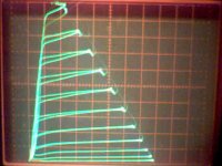
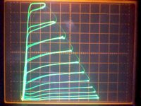
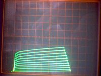
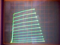
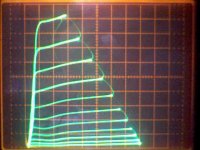
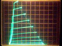
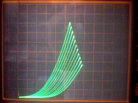
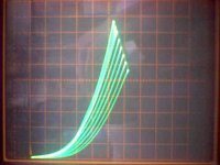
Just for fun, here are some curve sets for the 6P1P 4400 tube without and with an applied magnetic field. This was done with a fairly strong ferrite refrigerator magnet. Surprisingly, the effects shape does not change much with direction of field, just the magnitude of the effect (ie, same rounding of curves). Greatest effect was with the field axial along the tube length.
Interestingly, the magnet gets rid of the hysteresis effect while it is applied (comes back after removal of the magnet). Although, the curves are pulled out of the region where this occured before without the magnet, so maybe not so surprising really. The avg. screen current goes up from 6 mA to 9mA with the magnet applied. The drooped curve shapes look similar to putting a large resistor in the g2 circuit or putting a non optimal negative voltage on g3 for some tubes. Maybe interesting for modifying the harmonic structure of the tube gain. But looks like g2 dissipation must go up substantially.
Repeated application of the magnet does not seem to leave any permanent effect on the tube, although it is apparent that the tube is constructed with magnetic materials from its attractive force. Maybe the internal temp is too high to allow any permanent magnetizing effect.
edit: added 3rd image with half magnet effect
---------------------------
Just for fun, here are some curve sets for the 6P1P 4400 tube without and with an applied magnetic field. This was done with a fairly strong ferrite refrigerator magnet. Surprisingly, the effects shape does not change much with direction of field, just the magnitude of the effect (ie, same rounding of curves). Greatest effect was with the field axial along the tube length.
Interestingly, the magnet gets rid of the hysteresis effect while it is applied (comes back after removal of the magnet). Although, the curves are pulled out of the region where this occured before without the magnet, so maybe not so surprising really. The avg. screen current goes up from 6 mA to 9mA with the magnet applied. The drooped curve shapes look similar to putting a large resistor in the g2 circuit or putting a non optimal negative voltage on g3 for some tubes. Maybe interesting for modifying the harmonic structure of the tube gain. But looks like g2 dissipation must go up substantially.
Repeated application of the magnet does not seem to leave any permanent effect on the tube, although it is apparent that the tube is constructed with magnetic materials from its attractive force. Maybe the internal temp is too high to allow any permanent magnetizing effect.
edit: added 3rd image with half magnet effect
Attachments

Last edited:
G2 normally hides in the shadow of G1. But you put a magnetic field axially.
Doesn't this shift the apparent shadow? Maybe why G2 current changes?
Maybe this is useful when running positive G1? I worry G2 might be in focus
of A2 beams rather than shadow... Shifting the pattern might correct this?
I've never Xrayd 1P, so I don't know if grids even have such an alignment.
If shadowing is random, then I'm baffled what makes the current change?
Last edited:
Hi Ken,
The 6P1Pev has slots you can see thru, so I just checked it with a magnifying glass and it definately has aligned grids g1 and g2. g3 is a beam former plate. Being a beam tube, my theory of a g3 gas dielectric coating seems unlikely here (shouldn't have much effect). Can't see any obvious differences between the two tubes either except that the hysteretic one has its grid alignment off just a hair, the other is spot on.
I would imagine that the magnetic field is curving the grid wire beamlets to hit g2 wires here as you suggested. Doesn't seem likely to me that one could correct for a positive g1 this way. The shadow grid tubes (6GU5, 6FG5, 6FS5 ) have another aligned negative grid betwwen g1 and the usual "g2" that guards "g2". These tubes used a high gm frame grid for g1 which couldn't be aligned with "g2". I'm not aware of any power tubes that had this feature though, but should work for a positive g1 I would think.
Last edited:
The combined g2,g1/Mu drive scheme seems like a practical solution for positive g1 and g2.
This only requires half the positive voltages of positive g1 only drive (and g2 need only go half as positve compared to fixed pos. g2 and neg. g1 drive). Grid currents scale like square law of pos. voltages I think. The plate voltage can then drop lower too (before going below g2 voltage).
This only requires half the positive voltages of positive g1 only drive (and g2 need only go half as positve compared to fixed pos. g2 and neg. g1 drive). Grid currents scale like square law of pos. voltages I think. The plate voltage can then drop lower too (before going below g2 voltage).
Last edited:
The combined g2,g1/Mu drive scheme seems like a practical solution for positive g1 and g2.
This only requires half the positive voltages of positive g1 only drive (and g2 need only go half as positve compared to fixed pos. g2 and neg. g1 drive). Grid currents scale like square law of pos. voltages I think. The plate voltage can then drop lower too (before going below g2 voltage).
Totally. I think it makes a 2 stage screen drive amp a possibility. A couple of MOSFET followers and <=150Vpk drive stage (which is not that hard) traded off against a stable screen supply and a negative bias supply that you don't need... At the lower drive voltages vs. g2-only drive it would work with parallel (shunt) plate-grid feedback. Plate efficiency goes up a few % in class AB for some test cases of 50W PP sweep tube amps using 17W tubes. Quiescent current can also I think be reduced as the transfer function seems more linear.
Michael
FYI, tubes are usually built with nickel, an excellent ferromagnetic element (and half the content of such legendary alloys as permalloy). Ni's curie temperature is 358C, so most of the components inside an operating power tube will be demagnetized (above the curie temp.), though not necessarily a tube on the curve tracer.
When you apply a toroidial magnet, you're bringing a dipole field near, which is basically all fringing flux. This means the field is diverging above and below the magnet. Since electron paths are bent perpendicular to the field lines, you will get an axial spiraling, which will tend to move the beam of a beam tetrode away from the plate seam and towards the suppressor plates and grid supports. Since the field is divergent, electrons will also be bent up or down, which will increase screen current. One might speculate on the effect of secondary emission (which seems to be worsened, although only at high current, as in a pentode, not to the point of negative resistance at low current density, as in a beam tetrode), but I don't have a convincing explanation for that.
And note this doesn't even take into account the channeling of flux inside the magnetic components, which should act to reduce divergence (except at the open end, on top) and make a somewhat more uniform distribution of magnetism along the length, butbe left with localized spots of higher intensity (such as supports, corners, cold spots, etc.).
Hmm, now I wonder what a tube does when hot. That could be tested by building a standard magnetization fixture (i.e., a glorified solenoid around the tube, with calibrated currents applied), and testing after running at rated power for a few minutes (so the structure is hot, past the curie temperature in places). Then watch how it changes as it cools down.
Tim
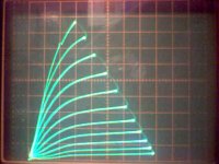
As TubeSteve says, 6P1P appears to be identical in specs to a 6AQ5, which has a g2/g1 Mu of 9.5. So I rigged up the 6P1P 4400 (hysteretic) with g2,g1/Mu drive using a 1K Ohm resistor from g2 to g1, and a 100 Ohm resistor from g1 to cathode. Drive on g2 at 5.3 V/step.
Plot1: g2,g1/Mu, 50 V/div horiz., 5 ma/div vert., 5.3 V steps
Plot2: g2 only, ditto, g1 at 0 V
Plot3: g2 only, but changed to 2 mA/div vert.
Seems to still have hysteresis in g2,g1/Mu mode. Still a bit in g2 drive only too. Plot 1 versus Plot2 verifies that each grid is doing half the control.
I also tried banging this tube hard on a vinyl floor mat to see if I could affect the g2/g1 alignment, but couldn't see any difference, and the hysteresis stayed the same too.
-------------------------------
On the g2 current with positive g1 thing again, I've been thinking that maybe a tube with 180 degree g2/g1 alignment (g2 wires exactly in between the g1 wires) might be the ideal arrangement to avoid focusing current onto g2 wires. If I ever see some very badly aligned tube I'll test that.
--------------------------------
edit: added the non hysteretic 3950 6P1P tube in g2,g1/Mu mode for comparison, same scale as Plot1. Curves look great in g2,g1/Mu, no rounding at all.
Attachments

Last edited:
"When you apply a toroidial magnet"
I tried a simple axially symmetric rectifier tube, 19Y3, in a magnetic field from a stack of strong toroid magnets here. They are stacked about 4 inches high and slipped over the tube for the axial case. Perpendicular case has the tube stuck to the end face. Scale for plots is 2 V/div horiz. and 10 mA/div vert.
Plot1: no field
Plot2: axial field case
Plot3: perpendicular case
I tried both directions of the magnetic field for the axial case, and they were the same as expected. Also tried both polarity fields for the perp. case, and the same result.
Looks like an axial field works well for increasing the plate resistance.
Should be interesting to try this on an axial sym. triode to see if it affects the Mu or not.
Edit: added earlier plots as plot 4 and 5 here of the 6P1P in normal g1 drive mode for comparison with the previous g2,g1/Mu and g2 plots shown above. Plot4 has 100 V on g2 and Plot5 has 200 V on g2.
Attachments
Last edited:
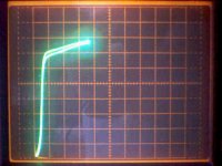
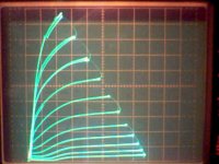
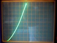
Here are some curves for a 6S4A triode with axial magnetic fields. This tube has a circular cathode, the grid is crimped around the cathode (nearly round) from further out posts and the plate is flat type.
Plot1: normal triode operation, 50 V/div horiz., 5 mA/div vert., 1.2 V steps g1
Plot2: axial field along tube, ditto, same grid bias as above: 0V grid for max curve
Plot3: axial field along tube, ditto, adjusted grid bias positive for max curve
Seems that the electrons can't get past the grid with positive grid in Plot3. Must be spiralling into the posts.
Appears that Mu and gm got decreased in Plot2
Attachments
Last edited:
Looks like an axial field works well for increasing the plate resistance.
Hmmm... Is a current limiting rectifier already patented? Just put a rectifier tube inside of a choke ...
Still, mysterious why some tubes do the hysteresis thing and others don't.
Different tension of the 1'st grid, so temperature changes geometry differently?
- Home
- Amplifiers
- Tubes / Valves
- Suppresor Grid used for Feedback?