The complete circuit shown is another one of my wild ideas. It is a completely DC coupled class A, fully differential amplifier. I have another simulation that uses vacuum tubes in the output stage. I plan to test these sometime soon.
Where is your output - can't tell by the simulation pic. Drain of the mosfets?
It would be very cool if you could model individual speakers accurately too...
Where is your output - can't tell by the simulation pic. Drain of the mosfets?
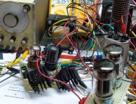
The test points in this picture were the plates of the second stage. There is also a blue trace that is nearly invisible in this photo.
This thread is about a 6L6GC based P-P amp. There have been several itterations of a driver for said amp, and this circuit with the mosfets rewired into a PowerDrive configuration could be a suitable driver. That is what was running on my bench last night. 6L6GC's and other tubes will get wired in at my next opportunity.
It would be very cool if you could model individual speakers accurately too...
I'm using a free simulator. It can only do so much, and the accuracy is highly dependent on the device models. The vacuum tube models that I use have been sourced from all over the net and vary from good to totally useless.
This thread is about a 6L6GC based P-P amp.
yes, I've been lurking... wondering what the next TL PCB will be.
I'm using a free simulator. It can only do so much
I agree, but for a free sim, LTSpice is pretty flexible. Good luck on your experiments...
yes, I've been lurking... wondering what the next TL PCB will be.
The Simple P-P has been sent to the PC board shop. It is a push pull amp using EL84's, 6BQ5's or 7189's. I must shoot all of the pictures for the manual when it returns. The time frame depends on my work schedule.
I sent it out earlier this year, but had to cancel the order when my wife lost her job. Tubelab has never made any money, but came close last year. This year I must watch expenses very closely.
After that brings in enough money to recover the costs, the Spud SE will get sent out. Both of those designs were finished last year.
There will be more push pull designs, but nothing else is finished yet. There is zero budget for buying big things like transformers, but that is not a big limitation since I have been collecting tubes and transformers for over 20 years.
Another thread lurker here...
Offtopic: Tubelab, what about taking pre-orders to help fund board purchasing? Donations for R&D?
Offtopic: Tubelab, what about taking pre-orders to help fund board purchasing? Donations for R&D?
Tubelab, what about taking pre-orders to help fund board purchasing?
I feel uncomfortable about taking money for a product that I don't have ready. I must wait until I actually have the PC boards in hand to be able to shoot the pictures of one of them being assembled. I then can put together the assembly manual. I can not even hazard a guess as to how long this process will take because my work schedule is highly unpredictable. Our next pass of a custom linear IC is due in house at about the same time I will get the PC boards back. If the IC works great, I will be at work a lot. If it doesn't work at all, I could be unemployed! Somewhere in the middle ground would be nice. Sherri's mom is in the hospital again, so that is another wild card.
Donations for R&D?
The budget doesn't support buying much right now, but my stash of "stuff" could support my habit for several years. I really need to reduce my collection, so I have decided to see what I can make with what I already have. Now, if I could only remember where I put that pair of UTC LS-57 P-P OPT's I could actually build myself a 6L6GC P-P amp.
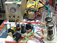
OK, back to the thread. Tonight I wired a pair of octal sockets up to the driver board. The OPT's at hand have no UL taps, so I wired the tubes in triode mode. At first I plugged in a pair of Chinese 6L6GC's and set the bias to 50 ma per tube with 400 volts of B+ (kind of hot). Power was about 17 watts at 5% and 23 watts at clip. Listening tests sounded similar to the previous tests. Previously I liked the sound of KT88's so..
In went the KT88's. I set them to about 50 ma, but cranked the power supply up to 450 volts. This is almost conservative for these tubes. I run the same pair of tubes at 100 mA in my Simple SE, also at 450 volts. Power was 24 watts at 5% and about 30 watts at clip. The pot that sets the input stage CCS was at one end of its range to get minimum distortion at full power. This means that more power may be available with more tweaking. I hooked up the CD player and cranked it up for about 5 minutes before Sherri strongly suggested that I turn it down! Diana Krall sounded amazingly clean, maybe better than the same tubes in the Simple SE, but not DHT quality yet. I tried some Depeche Mode, but this resulted in an unhappy spouse, so I pulled the plug. It is almost 11 PM here.
None of the tricks required earlier were required to stabilize the amp. It just worked. Adjusting the CCS's resulted in no funny stuff. There is a pronounced dip in distortion with a smooth increase on either side. No flip flop action and extreme overdrive just resulted in extreme clipping, no instability.
More testing and tweaking later.
Attachments
Sounding really great!
I have tried to update my schematic to represent the changes you have made. Your diagram of the Spice model did not come out that clear for me. I can see the layout, but the values are difficult to make out. It looked like 47K plate resistors on the first stage. It looks like you are wanting more current through the CCS than the 220R resistor is letting you get - limited to about 12-14mA from the datasheet. I subbed in 91R here to limit to about 28mA.
Anode resistors of the second stage looked to be 13K?
Grid of second triode in first stage looked like 500R to the negative supply?
I have seen designs with a balancing pot between anodes on the long tailed pairs. Would this be advantageous or unnecessary complication?
Have attached the schematic with these changes.
Regards,
Chris
Attachments
I tried some Depeche Mode, but this resulted in an unhappy spouse, so I pulled the plug. It is almost 11 PM here.
headphones? sound proofing?
oldmanStrat said:
headphones? sound proofing?
At these levels, Exploding head, exploding room... I can think of a few DP songs that would have the woofer pushing the xmax and getting the wife out of bed to ask me not to wake the baby 🙂
Chris. The grids of the first 6SN7's are returned to ground. I didn't change anything here from the initial design. Provision for feedback input is still present on the second triode in the first stage. I am currently experimenting with summing in a DC voltage here as well to allow DC offset correction through the entire amplifier. This may work better than a balancing pot, but more experiments are in order. The plate load resistors for the second stage were 18K in my simulation but 20K in the test circuit, because I had 20K resistors. The resistor labled R56 in your schematic is not needed. I will post an Eagle schematic once I get it where I like it.
The offending song was "Policy of Truth" and the volume control was just shy of clipping. Sherri was at the other end of the house trying to watch TV.
I can think of a few DP songs that would have the woofer pushing the xmax
The offending song was "Policy of Truth" and the volume control was just shy of clipping. Sherri was at the other end of the house trying to watch TV.
At these levels, Exploding head QUOTE]
I have never been a fan of headphones. My head sweats far too much for any pair I have ever tried to be comfortable. I have used the same pair of speakers to test amps for about 15 years. Any thing different would mean recalibrating my ears, probably a futile task.
exploding room...
Now there is a goal to strive towards. If the 833A powered guitar amp didn't do it, I don't think it is going to happen, certainly not with the little Yamaha speakers!
ask me not to wake the baby
Kids and grandkids live far far away. About 3000 miles, Even I can't get that loud.
OK, I just made one very simple change and now this thing ROCKS. DM, yeah the speakers are moving around on the bench. What makes them do that, OH, about 60 WATTS! in triode mode
My previous testing had revealed asymetrical clipping in the driver stage. This is caused by a small DC offset in the input stage being amplified by the second stage causing the plate voltages to differ by 35 volts or so depending on tubes. I wired the grid resistor that goes to ground on the second tube in the first stage up to a trim pot. The trim pot has a positive voltage on one end and a negative voltage on the other end. Only a few volts are needed. I'll post a schematic later. I did some basic testing, then cranked some tunes. I think this is getting real close to the "build an amp" stage, but I plan to do some more tweaking later. Right now Sherri wants to go see Harry Potter, so we are off to fight the crowds.
Some real measured data with the EH KT88's at 450 volts. Bias was increased to 70 mA, this didn't change the numbers much but improved the bass on DM. Other voltages are as before +25 and -105 on the other supplies, The new pot tweaked for minimum distortion at the edge of clipping:
Test #1 6600 ohm load triode mode:
THD at 1 watt 0.27%
5 watts 0.46%
10 watts 0.72%
20 watts 1.08%
30 watts 2.59%
35 watts 3.84%
38 watts 5.01%
40 watts 5.86%
45 watts 9.36%
Test #2 3300 ohm load triode mode
THD at 1 watt 0.36%
5 watts 0.48%
10 watts 0.84%
20 watts 1.36%
30 watts 1.61%
40 watts 2.19%
50 watts 3.57%
56 watts 4.99%
60 watts 6.07%
I get more power and the amp is definitely louder with the 3300 ohm load, but it sounds better with the 6600 ohm load. All testing was done without any feedback. The sound could improve on the 3300 ohm load with a little bit of feedback.
George,
Your setup is starting to look very similar to the one that I burned up my KT88s with. Which MOSFETs are you using? Mine (FQPF2N90) show some steeply rising Crss at about Vds = 7. You may get a good reduction in distortion from raising the +25 positive rail. On the other hand, this probably limits the damage you can do to the grids of the tubes.
Do you have plans to measure driver distortion at the levels you are driving at? I would be curious to see how well the driver is performing.
Which MOSFETs are you using?
The board used for the previous experiments used some Toshiba 2SK2700's which have become very hard to find. I used that board for so many experiments that it was falling apart. I dropped it twice which didn't help since the heat sinks are not mounted to anything. This ripped one of the mosfets right off the board. So, what to do?
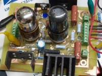
The very positive results from Saturdays testing convinced me that I need to build an amplifier based on this design. Since my board was in pretty bad shape, I decided that I needed a new one. Saturday evening I laid out a new PC board. I made two of them. I don't have any good way to trim the board to size here at the house, so I just rough cut one of them with a Dremel tool. They will meet the band saw tomorrow night at wood shop class. I populated one board Sunday night. This one used Toshiba 2SK3563 mosfets. These are available at DigiKey. They are in an insulated package which helps to avoid shocking moments when poking around on a live board. The Crss is a constant 7 pF in the voltage ranges used here.
It is one thing to make one working amplifier. It is another thing to make several without needing to optimize each one. So tonight I fired up the new board. I popped in only the input tube and seth the pots for 160 volts on each plate. I then popped in the second tube and set the pots for 350 volts on each plate. I set the bias to max negative voltage and added the KT88's.
Does it work? Oh yeah. This one makes 60 watts at 5% distortion which is slightly better than the last amp. I attribute this to the absolutely monster 600 uF ASC capacitor that I scored on Ebay that was wired across the power supply instead of the used cap robbed from a dead air conditioner used in the previous test.
Other than the slightly lower distortion and slightly higher power this board performed in an identical manner to the first one. There is one more board waiting to be built.
You may get a good reduction in distortion from raising the +25 positive rail. On the other hand, this probably limits the damage you can do to the grids of the tubes.
I got my EH KT88's for $10 each. I really don't want to blow them up. Right now the bench power supply that I am using only goes up to 25 volts. I have already decided to build an amp using these boards (thats why I made two). I have not decided which output tubes or transformers this amp will use, or even how much power it will make. I have yet to explore how the board will work at voltages above 450 volts. So, I have a whole bunch of experiments to try, but I wanted to nail down the design so that Chris could build his amp. I have a carton (25 tubes) of older (15 years old) Chinese KT88's. These will remind you that the Chinese invented fireworks. I wouldn't mind exploring the upper limits of grid current with some of these!
Attachments
Do you have plans to measure driver distortion at the levels you are driving at? I would be curious to see how well the driver is performing.
I plan to make these and other measurements as soon as I have time. I need to get my FFT analyzer hooked up so that I can see the distortion profile.
Below is a picture of the new board. It has not been trimmed to size yet.
Attachments
Here is the eagle schematic that was used to make the board. Somewhere around here I have at least 6 brand new Chinese 6L6GC's. I will tese these to see what they will do, and I plan to hook up some sweep tubes. I don't think that this board will produce enough drive voltage for screen driven or cathode follower applications. Only time will tell.
I'll make a parts list as I populate the second board.
I'll make a parts list as I populate the second board.
Attachments

I think I just found the bypass caps for my electrolyticless Simple SEtubelab.com said:I attribute this to the absolutely monster 600 uF ASC capacitor that I scored on Ebay
😉
I think I just found the bypass caps for my electrolyticless Simple SE
Cheap too. I got 6 caps delivered for about $40. search Ebay for ASC 600
- Status
- Not open for further replies.
- Home
- Amplifiers
- Tubes / Valves
- 6L6GC AB2 Amp