That's how I'd do it.
The resistor above the CCS seems like it may not be necessary.
Your mosfet output is going to swing from -41V to 0V, so +/- supplies for the mosfet need to exceed those numbers.
It seems like Eli has used IRFBC20 in similar situations, ask him how much voltage it needs to perform well. I use FQPF2N80, which is another option. Isolated case and Crss is quite low for a fet that can handle that much power. I always give it plenty of voltage, so I don't know how it performs if you try to squeeze it down.
Thanks SpreadSpectrum,
The front end is a direct copy of Eli's "El Cheapo", so can't comment on the resistor above the CCS, in the original it is a 10K 1W CF. My knowledge of solid state devices is even poorer than my knowledge of vacuum tubes, so this is a bit of a challenge for me") If this topology is looking OK, I have to work out how to power it. I think I am going to go the way of regulated B+. That will require then a regulated -ive bias. The power transformer I have does have a 50 volt tap, so that should be OK for the bias supply (?). I need a little guidance for the power supply of the mosfet. Do I need a totally separate supply for them? Can I feed the -ive supply for the mosfet from the -20.5 volt output tube bias? Can the +ive supply come from a tap from the regulated B+? What grid current should be designed for?
If this topology is looking OK, I have to work out how to power it. I think I am going to go the way of regulated B+. That will require then a regulated -ive bias. The power transformer I have does have a 50 volt tap, so that should be OK for the bias supply (?). I need a little guidance for the power supply of the mosfet. Do I need a totally separate supply for them? Can I feed the -ive supply for the mosfet from the -20.5 volt output tube bias? Can the +ive supply come from a tap from the regulated B+? What grid current should be designed for?
I am sorry for the amount of questions and guidance being asked for, but I think I have a head like a sieve at the moment!
Cheers,
Chris
The front end is a direct copy of Eli's "El Cheapo", so can't comment on the resistor above the CCS, in the original it is a 10K 1W CF. My knowledge of solid state devices is even poorer than my knowledge of vacuum tubes, so this is a bit of a challenge for me
If this topology is looking OK, I have to work out how to power it. I think I am going to go the way of regulated B+. That will require then a regulated -ive bias. The power transformer I have does have a 50 volt tap, so that should be OK for the bias supply (?). I need a little guidance for the power supply of the mosfet. Do I need a totally separate supply for them? Can I feed the -ive supply for the mosfet from the -20.5 volt output tube bias? Can the +ive supply come from a tap from the regulated B+? What grid current should be designed for?I am sorry for the amount of questions and guidance being asked for, but I think I have a head like a sieve at the moment!
Cheers,
Chris
The resistor above the CCS seems like it may not be necessary.
I don't know about Eli, but I use the resistor there for two reasons:
1. To take up some of the dissipation from the CCS.
2. To somewhat isolate the CCS's capacitance from Cdg.
I need a little guidance for the power supply of the mosfet.
OK, there are three places in your circuit that need a negative voltage source. It is possible to derive them all from the same negative supply but I doubt that the bias tap on the power transformer will work.
First off the CCS in your schematic is shown as being connected to ground. Depending on the choice of input tube and bias points the CCS will only have a volt or two to work. Morgan Jones made this work using an LM124 and a 6J6 tube, but most CCS's need more voltage. My old favorite the IXYS 10M45 needs at least 15 volts to be happy redardless of what the data shees says. All semiconductors exhibit voltage variable capacitance effects which are reduced by raising the voltage. You need something between -15 and -450 volts if using a 10M45. Regulation is not important.
The mosfet source is connected through a resistor to a negative voltage source. This voltage must be more negative than the peak negative drive voltage. In reality you need quite a bit more voltage. You need enough voltage to assure cutoff of the output tube. I like to have enough voltage to assure continuous current through the mosfet as the tube approaches cuttoff. The mosfet can source plenty of current into the grid of the output tube for AB2 or instantaneous overload, however the source resistor and negative voltage source must discharge the miller capacitance of the output tube to recover from overload. This is not such a big deal on a pentode , but is a big problem on say an 811A. I would go for - 100 volts or more. Regulation is not important, but the supply should be clean.
The bias pot is connected to a negative voltage source. Again I like to be able to adjust the output tubes to cutoff when bringing up a new amp, so you need at least -45 volts here. It was stated previously that the bias supply must be regulated if the plate supply is regulated. In reality the plate supply is not important it is the screen supply that controls the current through a pentode. The screen and the plate are the same supply in UL or triode, so if this supply is regulated, the bias supply must be regulated. The entire supply does not need to be regulated, just the source for the bias pot. A zener or gas tube is sufficient.
Why can't you use the bias tap on the power transformer? The Hammond transformers only have the tap on one side of the center tap (one purple wire). This means that you would only get to use a half wave rectifier. Normally this is used to supply a few microamps to a bias pot, so a half wave rectifier is common. However the mosfet works best if fed a few milliamps, which may make getting a clean supply difficult from a half wave rectifier.
What would I recommend? Well I have built several PowerDrive test boards that have been used in 6L6 type amplifiers among others. You are also going to need a positive voltage source to feed the drain of the mosfet. The easiest way to get there is to use a small isolation transformer that has two 120 volt windings. Wire them in series to make a 120-0-120 volt winding. I use a bridge rectifier with the center tap grounded to make +150 and -150 volts in a manner similar to most solid state power amps. This feeds the mosfet its + and - supplies. It also feeds the negative voltage to the CCS on the input stage. I use a zener diode and a resistor to make -68 volts from the -150 volt source.
I like the LTP type of phase splitter. I tested it using several types of tubes when developing the Simple P-P. I found that the gain was barely adequate to drive a pair of EL84's. There was not enough gain to allow the use of negative feedback or triode connection. I have not tried the 7591 tube, but I am not sure that a single stage LTP will be enough if you ever want to try 6L6's or other tube types, and it won't be enough if you want to run 6L6's in triode, which is what I found to be my favorite choice to get about 20 watts.
Your universal driver looks VERY interesting. This project is going to take a little time, so will follow your schematic development with great interest! Since my space in the chassis is not that great, I think that waiting for the development of the driver PC board would work well for me.
I have been working on this driver on and off for a long time. There are several influences in my life right now that have killed much of my tube time lately. I have realized that I went through all of 2008 without completing a single amplifier. That won't happen in 2009. I can't say when the PC board will be completed, or if funds will be available to get a batch made, so don't wait on me. I have just finished laying out the first proto board. I made two of them and have started populating one of them.
I have already received a few emails asking questions. Its late here and I need to get up early tomorrow, but I will start another thread at my next opportunity to post progress, testing, photos, and yes, schematics.
Thanks for taking the time to post such a comprehensive response George. Much appreciated. Yes, I made a mistake in my representation of the CCS in the LTP of the "El Cheapo". It is attached to a B- supply. I will keep an eye out for a suitable +/- supply transformer. Unfortunately I am in a 240 volt country, so a 120/120 isolation transformer is not my answer. I will be in Singapore next month, so will have a browse around Sim Lim for suitable.
Something like this may work Chinese R core transformer R26-42 50 watt, 115x2 primary, 0-50-55(0.45A) x 2 secondary. Wired with primaries in parallel would give about +/-75 volts, or primaries in series +/-150 volts @ about 200mA. Should also fit under chassis without too much trouble.
Now, the gain problem with the drive stage. I would like these mono blocks to have "standard" sensitivity. Should I re-think the driver tube and keep the topology, or do I need another drive stage? Perhaps revert to the original suggestion of using 12AT7 driver DC coupled to ECC99 LTP suggested by Eli?
Thanks again,
Chris
One other thing to note- the source follower driver will not need to be run in class A. As it swings negative, the tube is cut off and doesn't much care what the MOSFET is doing. So you can get away with a relatively low idle current, even though peak current will be much higher (on positive spwings).
G'Day hoka,
There is no schematic
I have started to collect non-critical parts such as output transformers, power transformer etc... I have been very busy with personal issues for the last couple of months, have not sorted out a workshp area after my move last year and university has just started for the year again this week!
The guys on this forum have been very helpful, but the design has not quite crystallised yet. To be honest, after starting the thread thinking I would be doing a scratch design point to point, I am waiting to see what happens with Tubelab's universal driver board. It looks to be the very thing to drive just about anything! I know that George has quite a lot on his plate at the moment with work and family issues, so I am happy to wait for things to happen "in the fullness of time". If someone has some further advice on the direction of this design in the mean time, that would be wonderful too!
Thanks again everyone!
Chris
I am waiting to see what happens with Tubelab's universal driver board.....I know that George has quite a lot on his plate at the moment with work and family issues
Unfortunately the board has been sitting half populated on my bench for a couple of weeks now along with a big box of tubes and a really big power supply. Sherri (my wife) has been home for exactly 4 days this year. She will be arriving tomorrow for 18 days so it is a safe bet that the board will be untouched for the next 18 days.
There will be several push pull amplifier designs that will come out of this complete with schematics, but at this time, I can't say when.
The way things are with me at home at the moment, I think that if I started another amp build right now my partner would cut my manhood off with a rusty knife and nail it to the front door!
We all appreciate what you have given to this forum and to the world of DIY tube amps George. Take the time to do what is really important. We can wait...
Regards,
Chris
We all appreciate what you have given to this forum and to the world of DIY tube amps George. Take the time to do what is really important. We can wait...
Regards,
Chris
chrish said:
We all appreciate what you have given to this forum and to the world of DIY tube amps George. Take the time to do what is really important.
AMEN!
My personal situation has changed a little recently. For various reasons I have had to defer university study this year. That frees up a lot of time to deal with those issues, and also should allow me some time to apply to my hobbies. Also, after moving from a modest sized house with garage in the country to an apartment, I have had no workshop space. My partner has a garage a few blocks away in the same street. I have had a bunch of my woodworking tools and machines stored there. A buddy of mine has just bought most of this equipment from me, so my partner is allowing me to use the some of the space freed up to set up a small workshop. Hopefully in a week or so I should be in a position to be able to start building stuff again!
As an aside, I have recently found out I have AS (if you don't know what AS is, don't worry - not a terminal disease...), and this hobby of researching and building electrical/audio/tube stuff is my 'special interest'. I use it to recharge my batteries and relax, so after a very hectic year, I am very much looking forward to making a start on this project.
I have re-read much of the last few pages, and would appreciate any guidance on a final design concept. The real issue is two or three stage driving mosfet source followers to output 7591. I am not sure how close Tubelab is to having his driver board finalised. It would be great to use, but I understand the pressures he is under and if there is to be no board in the near future I will probably scratch build something close to his design.
If you are listening George, what driver tubes were you using when you were breadboarding your driver? Any suggestions for best setup of driver config for 7591 or 6L6 style tubes using your universal schematic prototype?
Thanks again for all the help from everyone. My biggest problem is going to be sorting through all the great advice and help to patch together something that will work
Chris
I could be wrong, but I think that George's board was for large voltage swings. If you plan on using 7591s, you don't need large voltage swings from the driver. However, if you are going to build a driver that can swing some volts, you could use triode connected 6L6s instead of 7591s for more linearity and lower output impedance. With the 7591s, you can get by with a lot less voltage amplification and maybe one less stage.
There are advantages to using the 7591s and advantages to using other tubes. You just need to think about how you want to do it.
There are advantages to using the 7591s and advantages to using other tubes. You just need to think about how you want to do it.
As an aside, I have recently found out I have AS (if you don't know what AS is, don't worry - not a terminal disease...), and this hobby of researching and building electrical/audio/tube stuff is my 'special interest'.
OT: That Asparagus stuff is this year's fashionable diagnosis. It's a label slapped on anyone who likes to focus on problem solving or technical stuff in a stereotypical male way.
Ten years ago, you'd have been a Terminal Geek. Now, you have a syndrome.
SY said:
OT: That Asparagus stuff is this year's fashionable diagnosis. It's a label slapped on anyone who likes to focus on problem solving or technical stuff in a stereotypical male way.
Ten years ago, you'd have been a Terminal Geek. Now, you have a syndrome.
When I found out, I thought of this forum and thought that I was probably in pretty good company
I guess that I have been so loose with my design goals that it is difficult for people to give some focussed advice. I think I need to start making some decisions.
Amps will be monoblocks built in to the two aluminium chassis mentioned previously (9" * 14" * 2 1/2").
Output stage will be 7591 PP in to Tamura F684 6.6K 30 watt output transformers.
PP Ultralinear AB1 fixed bias 400 volt supply voltage. Bias -20.5 volts. Peak AF grid to grid voltage 41 volts. Output 32 Watts at 1% THD. As per Tung Sol 7591 data sheet.
This will be two stage. 12AT7 long tailed pair with CCS driving Mosfet source followers to the output stage. Front end as per "El Cheapo".
Power supply will be driven by two Hammond 300BX transformers 800VCT 250mA. Voltage will be regulated 400 volt with Maida style regulators with adequate heat sinking.
+/- supply to be determined for mosfet and bias. Most likely as per Tubelab suggestion +/- about 100V transformer, to be determined by availability (I live in 240 volt /50 Hz mains country).
My nature is to want to build something that is tweakable, like my Tubelab Simple SE. I can play with feedback, tube type with selectable cathode resistors, ultralinear or triode mode all with the flick of a switch. The reality with the amp is, however, that having found the valves I like and the type of amplification and feedback, I pretty much just leave it alone. My temptation with this amp is to be able to do similar things, ie, switch triode/ultralinear or be able to try different valves (I am aware of different pinout of 7591 to 6L6 and similar). I suspect the reality is to pick what I want and then optimise for that configuration for best results.
The limitation with a two stage setup is that I may limit myself in the future should I decide that I want to try a 6L6 amp in triode mode for example. My proposal is to take Tubelab's advice and perhaps regulate the bias supply with an octal gas discharge tube. This would provide some "eye candy" and also if I decided to revert to a three stage design in the future, I would not need to attack the chassis. I could then do something like a 6SL7 voltage amp with ECC99 LTP and use sand to regulate the bias perhaps...
Anyway, is this starting to look like a reasonable plan? I suspect with something more firm proposed it will be easier for the gurus to help nudge me in the right direction.
Ongoing input and suggestions most welcome.
Regards,
Chris
I could be wrong, but I think that George's board was for large voltage swings.
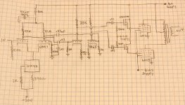
I am trying to come up with a design that can be used for common audio tubes like the 6L6GC and also do big voltage swings with suitable modifications. I have included my old screen drive schematic for reference. The schematic for the newer board is in the "universal" P-P driver board thread. They are both similar. For large voltage swings the coupling caps (.47 on this cshematic) between the first and second stages are necessary so that the second stage can operate with its cathode near ground for maximum output swing.
For more reasonable drive requirements the caps are replaced with jumpers so that the second stage operates with a cathode voltage in the 100 volt range. This requires a CCS in the cathode or a much larger cathode resistor.
The universal driver board has provisions for either a cathode resistor or a CCS chip in the cathode. It also has provisions for either plate load resistors or CCS's in the plate circuit. This makes for a complicated looking schematic, but it also makes for a "universal" design. For "normal" drive voltages a jumper wire goes in place of the coupling caps, and the driver would use either a CCS in the cathode with a resistor in the plate or a resistor in the cathode and CCS's in each plate circuit. The board can go either way.
If you are listening George, what driver tubes were you using when you were breadboarding your driver? Any suggestions for best setup of driver config for 7591 or 6L6 style tubes using your universal schematic prototype?
I have breadboarded 3 of these things. Each had a different tube line up. The original (the included schematic) had a 6BQ7 for the input tube and a 5965 for the driver. These were selected for maximum drive voltage output with good distortion. There are dozens of tubes that would work fine for more reasonable drive levels.
The second board (the tag board shown in the previous thread)used a pair of 6SN7's. I started with a 6SL7 for the input tube but a 6SN7 just worked better. These would be excellent tubes for a more reasonable output voltage requirement.
I had another tag board version with 9 pin tubes. I tried several different tubes and most worked. The best choices for input tubes were 5751's, 12AY7's, and 12AT7's. The best choices for driver tubes were 6GC7, 12BH7, and 5965. There are plenty of other tubes that should work, but I haven't tried them yet. Based on previous experience and stash on hand, I plan to use a 5751 in the first stage and a 6CG7/6FQ7 as the driver in the PC board version.
The limitation with a two stage setup is that I may limit myself in the future should I decide that I want to try a 6L6 amp in triode mode for example.
6L6GC's and even KT88"s in triode sound pretty good, so I would allow enough gain for their use. The same tubes in pentode mode with about 10 db of feedback is another possibility.
It is possible that I might have some time to experiment with this thing this weekend, but Friday isn't over yet. There is still about 4 more hours for something to go wrong.
Attachments
- Status
- This old topic is closed. If you want to reopen this topic, contact a moderator using the "Report Post" button.
- Home
- Amplifiers
- Tubes / Valves
- 6L6GC AB2 Amp