BTW Chris and George and everyone, this has been a fantastic and educational thread, thanks heaps!
ditto
If you are fussy about bias, i.e. each tube of each pair biased within a couple/few milliamps, then you would use a pot for each tube. If you are less fussy, or use matched tubes, then the second method, a pot for each pair.
maybe the fussy bias I need to opt for.
It's actually for the drivers of an OTL (circlotron), in parallel.
Fixed bias controls before the CF's that will drive the output tubes (6080).
So 1 bias control before the grid of the cathode followers I'm thinking.
I have a question regarding fixed bias.
I see some designs with individual fixed bias on each split signal.
Others I have seen fixed bias connected in the middle a matched resistor either side of the opposite rails.
In what situations do you use individually controlled fixed bias and just 1 bias control in the mid point between rails?
Fixed bias adjust for each final (what I do in my designs) has the advantage of allowing the balancing of the static (no signal) plate currents to reduce the possibility of DC core magnetization. This becomes especially critical for toroidal OPTs, as these cores include no air gap, and can't stand much DC magnetization.
One bias control for both finals is more "user friendly", but won't account for plate current imbalance any better than cathode bias. In both cases, you're likely to want matched pairs of finals.
If using a fixed bias to drive the grids on a 6080 am I looking at a 30-40 negative voltage requirement on each rail if the plate voltage is around 100-120 volts?
I heard when testing I should start at the most negative and slowly adjust until the required current is achieved.
I heard when testing I should start at the most negative and slowly adjust until the required current is achieved.
Attachments
😡😡
Breadboarded an OTL last night, with mosfets as the CF drivers.
Used a 50K trimmer from a -130 V source for each rails bias.
One rail bias worked great, adjustable 0 to -90 volts on the Source output BUT the other stuck at -1.2 volts. thought it was the mosfet, change that, still the same.
Head scratching and testing resistors for hours. Have to check the trimmer, maybe that is gone but doubt it.
But very strange the one that is working, I measured the positive voltage on the drain and it measures 32 volts, but the voltage is 130 volts.
The voltage on the drain that does not adjust properly is 64 volts from the 130 volt .
Bizarre to say the least.
Lost sleep over it last night.
Have to to check it all over again tonight.
I'd guess "wiring error." Can you sketch a schematic of what you THINK you wired?
You used gate stoppers, with the bodies of the resistors right up on the gate lead, right?
You used gate stoppers, with the bodies of the resistors right up on the gate lead, right?
I'd guess "wiring error." Can you sketch a schematic of what you THINK you wired?
You used gate stoppers, with the bodies of the resistors right up on the gate lead, right?
I'll check this when I get home tonight.
Gate stoppers need to be corrected. No they are not close up at the moment.
I wired it up as the same attached in this thread but yes have to double check. Maybe I didn't mirror both rails correctly.
I managed to blow up a mosfet last night. The negative voltage supply wire came lose and touched 2 of the pins of the mosfet. Sparks flew!!! Lol
Only have 3 left now🙁
Have another question about the grounding scheme.
It's the first time I have used separate power supplies for negative and positive power supplies.
Do I keep the grounding separate also or do I include all of the grounding points to a star location? (including the negative and positive power supply grounding points to the B+ power supply grounding point).
As they are separate now it makes it tricky to measure all voltages as I need to change to location of the ground probe each time. (having to remember which circuit it's on)🙄
Help please.
If I'm using a trimmer to adjust neg voltage bias, where is the ground connected (3rd pin)?
To the ground of the common ground on the B+ or to the ground of the negative power supply?
😕😕😕
Should the ground of the neg power supply circuit be connected to the common ground point of the B+ also? (or would this create a short circuit?)
😕
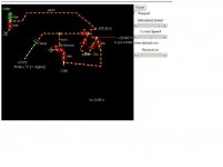
Ok I've got a circuit diagram here showing the mosfet as CF.
If I use a voltage divider to create the postive voltage for the drain on the mosfet, around 120 volts from the B+, this drops to zero after powering up.
As you can see from the rough simulation I end up with a negative voltage on the drain.😕
I have the negative voltage derived from a floating power source to power the source and bias.
(actually a 220/6v tansformer in reverse connected to a 12.3v heater supply to give me around -130 volts.)
I didn't expect the postive voltage on the drain would become negative.
Some advice would be greatly appreciated. Thanks.
How do I measure the negative grid bias?
If I measure from the negative power supply (ground probe) I get my required -XX voltage but if I measure with the ground probe to the B+ circuit I get positive voltages.
😕
Attachments
I suspect the issue is with the resistive divider from 350 to ground.
The thevenins equivelant circuit is 125V with a 64.3K series resistor to the drain of your FET.
You have 10mA of current flowing thorugh the circuit, so you have saturated your FET.
You need a lower impedance in the drain of the FET.
The thevenins equivelant circuit is 125V with a 64.3K series resistor to the drain of your FET.
You have 10mA of current flowing thorugh the circuit, so you have saturated your FET.
You need a lower impedance in the drain of the FET.
Last edited:
Thxs Gimp.
Looks like I'll need to derive the Postive voltage for the drain from a separate psu.
Looks like I'll need to derive the Postive voltage for the drain from a separate psu.
That or a FET with a greater Vds rating.
The IRFU310 is only s pecified for 400V, so with 350Vd and -130Vs you need a part rated for greater than 480Vds.
The IRFU310 is only s pecified for 400V, so with 350Vd and -130Vs you need a part rated for greater than 480Vds.
What about a zener divider? maybe 3 x 33v zeners in series with a resistor of low value.
99v on the drain and -130 volts on the source across the 10k resistor.
99v on the drain and -130 volts on the source across the 10k resistor.
biploar psu worked just fine. just need more power, only had about 20 watts to play with. but in theory it worked.
have to get a new transformer.
-18v grid bias to test on my otl. at 75 watts anode
6080 output 740mV on positive rail
and -720mV on neg.
Does that equate to 20mV dc offset ?
have to get a new transformer.
-18v grid bias to test on my otl. at 75 watts anode
6080 output 740mV on positive rail
and -720mV on neg.
Does that equate to 20mV dc offset ?
hey guys, i've been out of the loop with this thread for a few months; had to put my project on hold, but i'm looking to get back to work on it.
I was wondering if anyone could give me a rundown of this schematic posted by tubelab, i believe its intended to allow negative feedback from the OPT to the right hand grid of the first stage LTP (in this case pentodes) while also allowing an adjustable DC bias to be applied to this grid for balancing the anode currents of the two tubes of this LTP.
I'm just not sure exactly how it works :S
Thanks guys.
Attachments
Hi mnturner,
Fred here I think has a similar NFB idea and is well explained in his pages.
Hope this helps.
RA-100: Drivers and Power Amplifiers
Fred here I think has a similar NFB idea and is well explained in his pages.
Hope this helps.
RA-100: Drivers and Power Amplifiers
Thanks for the reply Brit01.
That schematic isn't exactly what I was talking about; Fred applies feedback to the grid of the left hand triode as though it were a simple common cathode amp. When using an LTP, I don't see why you would not use the grid of the other triode? Interesting read though.
That schematic isn't exactly what I was talking about; Fred applies feedback to the grid of the left hand triode as though it were a simple common cathode amp. When using an LTP, I don't see why you would not use the grid of the other triode? Interesting read though.
When using an LTP, I don't see why you would not use the grid of the other triode?
Not about the answer to that.😕
What would be the difference?
- Status
- Not open for further replies.
- Home
- Amplifiers
- Tubes / Valves
- 6L6GC AB2 Amp