Is there any particular reason that the bleed R for the -105V rail is 1M and the bleed R for the +75V rail is 220K?.......
I can't think of a reason unless Chris changed it to fix a problem. Both of these supplies should come up almost instantaneously, while the main B+ waits for the 5AR4 to light up. This is what you want, bias there quickly, B+ coming up slowly later.
I should have some time to play with my amp in mid February.....If "stuff" doesn't happen. It still kas the KT88's in it. Time to connect it to some big sweep tubes and rattle the house!
This is what you want, bias there quickly, B+ coming up slowly later.
I should have some time to play with my amp in mid February.....If "stuff" doesn't happen. It still kas the KT88's in it. Time to connect it to some big sweep tubes and rattle the house!
I'm planning on SS rectification, and I'm breadboarding the bias/mosfet rails with 470uf caps (Chrish has 220 uf called out).......so I hope the bias will still come up faster than the B+. I can always add a start delay; I have lots of amperites and other relays.
I'm planning 6SN7s into trioded KT88's into 5K OT's......so please post the results of your experiments....it's much appreciated.
I'm planning 6SN7s into trioded KT88's into 5K OT's......so please post the results of your experiments
The amp is still wired for trioded KT88's. I will probably get it all working in that configuration first, since it has been in the closet for about a year and a half, and has bounced off the floor at least once. I have some OPT's that can be wired for 5K.
Looking back, I ran the amp on an external power supply at 450 volts and tested it with triode wired KT88's with every load except 5K. The test with 3300 and 6600 ohms is in post #272 and 2500 ohms was in post #310.
Now that I have spent some time with Petes magic red board I want to run pentode mode with Schade feedback. I will probably try that with KT88's first before moving on to BAST's.
seeing a grown man cry.....
When building my Aikido a couple of years ago, I left it on top of a trash can in the garage one evening. When I closed the garage door, it caught the edge of the trash can, flinging the Aikido out onto my driveway.........smashing all of the tubes and denting the transformer....ouch. The boards were unscathed though.
.....and has bounced off the floor at least once.....
When building my Aikido a couple of years ago, I left it on top of a trash can in the garage one evening. When I closed the garage door, it caught the edge of the trash can, flinging the Aikido out onto my driveway.........smashing all of the tubes and denting the transformer....ouch. The boards were unscathed though.
smashing all of the tubes and denting the transformer....ouch.
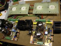
My amp is still in the breadboard stage. It is literally 4 PC boards screwed to a piece of Masonite. It has no transformers. The lack of weight prevented serious damage. It's been buried in the closet for at least a year, wedged in between the box for a ham radio and one of Petes red boards.
The amp is still wired for trioded KT88's.
I made that statement while I was at work this afternoon. Now that I am home and looked at the amp, I see plate caps. UH.....last time I played with tubes KT88's didn't have plate caps. I looked back at my notes and pictures. The last pictures were from mid 2010 and clearly show a pair of Mullard E130L's, so that's what the amp is set up for.
Attachments


G'Day Boywonder and George.
Interesting to see some new activity on this thread! From memory, I was having some problems with the -105 VR tubes striking as the voltage was marginal out of the 110 volt transformers. I tried reducing the current bleed on the bleed resistor, but ended up bucking some unused 5 volt windings from my main power transformer to increase the voltage so the VR would strike properly. There is no requirement to use VR tubes, I just had a hankering to include them in the design for the pretty glow.
I have not been doing much amp building lately, busy with university study and work. I was just plodding along with uni study, but now the (not so) brilliant managers of my company look like they want to destroy the business that has been around since 1920 (Australian flag carrier airline), so I had better finish before we go bust!
Did pick up a new toy yesterday from epay though, a power supply with variable 0-400v DC, variable 0 to -150 and fixed 6.3-0-6.3 VAC. Got it home and looked inside, it has 2 7 pin 0A2WA, a 6AU6W and 2 mallard EL34s as well as a very hefty power transformer and pretty big separate filament transformer. Will probably swap out the EL34s and save them and replace with some cheaper Russian types.
One thing I am thinking of doing to the amp in the future is using a little feedback or voltage divider at the input to reduce the input sensitivity. At the moment it is much more sensitive than my other amps and is a little difficult to balance volumes in a home theatre setup. If I were to build them again I would probably build the power supply on a PCB (I did not know how to do that at the time) and optimise the power transformer to the required voltage a little better so I did not have to drop quite so many volts (heat). I would also put the MOSFETs on heat sinks rather than use chassis as heat sink, as the chassis gets quite hot. Apart from those minor points the amps have been giving good service since built with no problems.
Cheers,
Chris
Last edited:
I was just plodding along with uni study, but now the (not so) brilliant managers of my company look like they want to destroy the business
Good luck. The company that I have worked at for the last 39 years used to pay for college. One of the benefits that gets killed when things start to sour is tuition reimbursement. I started college at age 37 and finished my masters degree at 46. All paid for by Motorola. I was about to enter the doctorate program when the plug was pulled. I can't complain, I got two college degrees and all I had to pay for was books....and I borrowed many of them.
a power supply with variable 0-400v DC
I have two of those, both purchased cheap at Hamfests. The Knight KG-664that I use a lot is a 200 mA versoin with 4 pass tubes. I got it for $20 and a promise that I was actually going to use it, not just steal the 4 new Winged C 6L6GC's and toss the rest. OK, I've been using it for about 10 years, so I guess its safe to put the Winged C's in an amp and some Chinese tubes in the power supply......
I have to pay myself. In Australia if you manage to get accepted for a government sponsored position, the fees are about $1000 a subject for a 24 subject law degree. Full fee paying is about double. I started in 2007 at 41 years old, will be 48 when I hope to finish. If I am lucky, Qantas will survive the current management and I will not have to use the degree. I don't really want to move away from home to the Middle East to keep flying, rather do something else and stay close to family...
The power supply looks like it was made in a Lab or commercial/military workshop. Scratch made aluminium chassis, but good turret board and laced wiring underneath. Have not had time to go through the circuit (I should be writing an assignment) but it looks like maybe one VR and EL34 for the 0 to -150 bias voltage and the other VR, 6AU6W and EL34 for the main dc supply. When I first turned it on I did not even know it was a tube powered supply. The -150 volts worked, but the main dc supply did not. When I opened it up I was surprised to see the two mullards in there. One was warm, the other cold. Reseated them and it worked. I did pay a little more than $20 though :-(
The power supply looks like it was made in a Lab or commercial/military workshop. Scratch made aluminium chassis, but good turret board and laced wiring underneath. Have not had time to go through the circuit (I should be writing an assignment) but it looks like maybe one VR and EL34 for the 0 to -150 bias voltage and the other VR, 6AU6W and EL34 for the main dc supply. When I first turned it on I did not even know it was a tube powered supply. The -150 volts worked, but the main dc supply did not. When I opened it up I was surprised to see the two mullards in there. One was warm, the other cold. Reseated them and it worked. I did pay a little more than $20 though :-(
Last edited:
the fees are about $1000 a subject for a 24 subject law degree. Full fee paying is about double.
When I started in 1990 the fees were about $650 USD per class in a private school. They were about $1000 when I left. State owned schools were $325 per class at the Masters level when I started in 1994 and about $360 when I left in 1999. I know that they have increased a lot in the last decade, but I don't know how much.
I was already an electrical enginner without a degree, but I got a bachelors degree in computer engineering and a masters in electrical enginnering. The company would only pay for something related to your career, or in some cases a potential career change within the company. That narrowed it down to engineering, marketing, business, and patent law. Of those, only engineering interests me.
The power supply looks like it was made in a Lab or commercial/military workshop.
Most of these used a similar schematic, but yours may be different since it wasn't the typical 1950's hobbyiest fare. Most designs use 2 or 4 pass tubes in the high voltage supply. Usually 6L6GC's or 807's. The negative supply is meant for bias and is just a pot. Don't short the negative output or the pot will fry.
I have the service manual for my Knight KG-664. It has 4 X 6L6GC, 1 X OA2, 1 X OB2, and 1 X 6DK6 (very similar to a 6AU6). It is PDF but I had to zip it to enclose here. I also have a PACO power supply. It has the same schematic but uses a smaller transformer and only 2 X 6L6GC and is rated for 100mA.
I did pay a little more than $20 though
They tend to sell for $100 to $200 here in working condition. Hamfests, especially the smaller ones are often a good place to find stuff like this just looking for a new home. The Knight was purchased new as a kit by the seller. He had used it through the 1960's, then it went into his garage. He took it out in the late 80's, retubed it and then lost interest in building stuff. He just wanted his baby to find a good home. I might have pushed the current meter into the red zone.....OK pegged it, a few timed but it still works good after 10+ years on my bench.
The PACO was a similar deal. It works but I have plenty of power supplies so I don't use it much.
Attachments
Thanks for the schematic, I suspect mine is similar, but with 2 pass tubes. Just pulled the two EL34s and -150 variable bias output worked normally...
I paid $100, so not too bad. There were 3 for sale, first went for $120, I got the second, but the third went for $50. If I knew it had the big transformers and 2 mullard EL34s, I would have bid on another!
I paid $100, so not too bad. There were 3 for sale, first went for $120, I got the second, but the third went for $50. If I knew it had the big transformers and 2 mullard EL34s, I would have bid on another!
An externally hosted image should be here but it was not working when we last tested it.
An externally hosted image should be here but it was not working when we last tested it.
Last edited:
I suspect mine is similar, but with 2 pass tubes.
The circuit was very common and used by several manufacturers from the mid 50's to the 70's. The two pass tube version was the most common. It was rated at 100 mA while the 4 tube version is rated for 200 ma.
The design runs from a raw supply of about 650 volts. The limiting factors are the tube dissipation at low output voltages and the transformer capability at high currents. Set the output to 50 volts and the tubes see 600 volts. At 100 mA output a two tube supply sees 30 watts per tube. Cheap tubes are glowing!
Use the power supply where we noamally run it...300 to 400 volts and dissipation is not a problem. At 300 volts out the tubes see 17.5 watts each. The limiting factor now becomes the power transformer. I know my "200 mA" supply can crank out over 300 mA at 400 volts for an hour before the transformer gets too hot. Your transformer is even bigger than mine.
A better design is the Fluke 407D. It uses a tapped power transformer so that there is less voltage drop across the pass tubes when the output voltage is set to a lower value. It has 3 X 807 pass tubes and is rated to 300 mA. I have seen mine put out over 500 mA before it gets excited and starts oscillating. The 407D is becoming expensive. I got mine a few years ago for $25 on Ebay. Shipping was $45 though. They are big and heavy.
The English service manual can be found here:
http://www.rainers-elektronikpage.de/FLUKE_407D_Service-Unterlagen.pdf
Your transformer is even bigger than mine.
I thought it is not how big it is, but how you use it 😀
When I built my SSE, I tried a pair of JJ KT88s in it, but preferred the JJ E34L and Russian 6P3S-E. So, I have a pair of KT88s sitting around doing nothing. I should be able to plug them in and get almost the same performance as the 4 tube 6L6 version? If not, it would probably not be too hard to mod it at some point to take 2 extra pass tubes. Looks like the transformers are up to it.
Cheers,
Chris
One thing I am thinking of doing to the amp in the future is using a little feedback or voltage divider at the input to reduce the input sensitivity. At the moment it is much more sensitive than my other amps and is a little difficult to balance volumes in a home theatre setup.
Cheers,
Chris
Is the two stage differential 6SN7 front end still appropriate if I'm building this as a power amp, triode KT88's no feedback and my preamp has switchable gain (12db or 29 db) for line out? It seems like I'll have way more gain than I need as well...........
Thought you might be interested....
This amp wound up quite a bit like the "Tubeosaurus Rex" from an Arthur Loesch design in Sound Practices and a similar amp from JC Morrison's Fi Tube Primer.
Add cathode followers after the driver stage, and you get this:
PS - I forgot to mention that I've heard a few of these, including a push-pull 300B version I built (but had oscillation problems due to my inept layout). A buddy just built a 6DJ8 > 6N6P > EL34 version. All have sounded really, really clean.
Last edited:
Hmm, don't know what happened there. OK, let me try again.
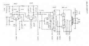
These are two schematics from the ca. 1992 Tube Audio Primer available from Don Garber's Fi store in NYC. J.C. Morrison drew up the schematics. It was wild and crazy stuff back then.
First schematic is a push-pull 6B4G amp that should look familiar.
Second schematic is basically the same driver circuit with cathode followers DC-coupled to 845's.
I hope you find them interesting.
--
Attachments

Is the two stage differential 6SN7 front end still appropriate if I'm building this as a power amp, triode KT88's no feedback and my preamp has switchable gain (12db or 29 db) for line out? It seems like I'll have way more gain than I need as well...........
I remember that with push-pull 300B's, it took something less than a volt input to drive the amp to clipping -- and that was with a -70V bias on the 300B's. That was with a 6DJ8 in the first stage. I used that type of amp with just a pot and switchbox, no active line preamp.
I figure the first 6SN7 LTP with 47k resistors in the plates would have a gain of what, about 15? So if the bias on the second 6SN7 is let's say -6V, then it will only take about half a volt at the input to drive the driver stage to full swing, right?
You could try 6N6P or 5687 instead of 6SN7, which should have a little less gain. A little higher distortion, though.
Reducing the plate load resistors on the first stage would also reduce the gain, right? I don't know what kind of a distortion penalty there'd be.
George, it sounds like you were thinking that a 6SL7 (or 12AT7 maybe?) would be necessary to give enough gain to play with plate feedback on the 6L6's. What if you only wanted an input sensitivity of about 2V rms to full power? Wouldn't the cascaded 6SN7's have enough gain for a little plate feedback around the triode KT-88's?
This amp is cool.
--
Wouldn't the cascaded 6SN7's have enough gain for a little plate feedback around the triode KT-88's?
The amp as it existed in the past spent quite some time wired up exactly that way. Cascaded 6SN7's driving trioded KT88's. With no feedback at all my CD player could drive it to clipping with even the quietist recordings. However there were a few DVD's that could not drive it into clipping using an old Toshiba DVD player. I like the sound of thst old beast so I keep it around even though I have to smack it sometimes to get it to play.
I figure the first 6SN7 LTP with 47k resistors in the plates would have a gain of what, about 15?
The standard aproximation for maximum gain in an LTP is half Mu, so the gain with an optimum load is 7 or 8.
Wiring the output tubes as pentodes raises the gain, but to compensate for the high output impedance of a pentode I experimented with some feedback. The setup that worked the best was to take a pair of resistors and wire them from the plates of the output tube to the plate of the opposite input tube. This wraps the feedback around the output and driver tubes. You need a 6SL7 for the first tube to make this work.
This amp wound up quite a bit like the "Tubeosaurus Rex"
I have been told of a few others that it looked like too. In fact there was a thread on this forum that contained a schematic of an amp that used a 6SL7 driving a 6SN7 driving some big pentode and it used cross coupled feedback connected just like I described above. I found it about a year ago, but can't find it now.
The standard aproximation for maximum gain in an LTP is half Mu, so the gain with an optimum load is 7 or 8.
This always confuses me. As I understand it, the gain is halved if one only looks at one output of the LTP. But since it's a push-pull thingie, it actually goes up halfway and down halfway at the same time, so combine those and you get the full swing (gain of +8 and -8 combined, makes 16 peak to peak).
If you look at the Crystal Palace schematic in Morgan Jones' book, he notes the gain of each stage, using LTP'd 6J5's. The first stage says "A = 17" and the second stage says "A = 18". I assume by "A" he means the amplification of each stage.
I hope I'm understanding that correctly. I've been struggling with that for some time now...
--
PS - Come to think of it, MJ's Crystal Palace is similar. Main difference is that he DC-coupled the driver stage to the cathode followers, instead of DC-coupling the input phase splitter to the driver... and 6J5 cathode followers instead of MOSFET source followers, of course.
--
Last edited:
May I butt in here, Tubelab? (Hi to you!)
One should look at one stage throughout, not the Vpp measuring 'across' both stages. Remember that at the end both 'halves' are added by inverting one in the output transformer.
Perhaps looking at the input arrangement will clear it up somewhat. With only one tube you have the signal input between the grid and cathode, connected to common (earth). With the LTP you have the same input, but now the cathodes are tied together with the 'bottom' grid at common this time. This means you now have the same input signal but spread (divided) over two tube inputs, thus each tube now sees only half the input. From there onwards you can still consider each LTP half as a full amplification stage, but now with only 0,5Vin for input. Hope this helps.
I do not have a Morgan Jones (so careful here), but the 'internal' amplification or µ of a 6J5 is given as 19. Normally A denotes the actual amplification of a stage taking circuit elements into consideration. That way I doubt whether one can get A as high as 18 from a µ=19 tube (respects to Mr Jones); more like 14 - 16. [To refresh: A = µ*Rl/(Rl + rp)]. Hope I am not overlooking something here.
Last edited:
- Status
- Not open for further replies.
- Home
- Amplifiers
- Tubes / Valves
- 6L6GC AB2 Amp