Hi Salas, as a big big fan of your designs I came across this thread. I looked through it and was wondering if there were any PCBs prototyped or made? Or you prefer p-t-p for this preamp? I never done anything tube so I am a bit afraid starting without a pcb
I never thought of making a PCB for this design as it is relatively low parts count tube and almost all builders in this forum's section are experienced. Plus the parts they got vary in size. Still, another one recently asked for a more defined concept as he was inexperienced in high voltage circuits building. Maybe I have to rethink about it. It might well be a Guinness World Records worth entry for an official board to be firstly released about a DIY design only eleven years after it was firstly discussed in a forum
You have my eager support!
Don't be intimidated by the lack of a PCB. Use point to point wiring with Bakelite terminal strips or tag boards.
Just follow common sense rules for building and troubleshooting and the high voltage will not be a concern.
Hello Salas:
I am also a relative beginner at tube amp and point to point building. I think there would be very big interest in a PCB for this circuit. There are many examples of good solid stable p-p designs that have been done as PCB's with great success. Baby Huey comes immediately to mind.
A PCB will definitely bring more DIYers into the tube world and get them excited about glass and fire.
I suggest you see if there is interest. I am interested for sure. Prasi from the BabyHuey PCB thread may be interested in being involved.
I hope this helps
Guys, I will see what can I do when I will be taking a "project-less" time out otherwise. I don't outsource layouts. I carefully pick the most likely parts and features, then I envision the layout, then my friend CRT does the CAD work when he has time. Working along my guidelines as we finish it up with back and forth nitpicking. Then test PCBs are ordered. In the end a real prototype build gets bench and subjectively tested. If I am not happy a redesigned and retooled PCB in minimum pcs is ordered again to construct and test again. Its a habit by now, maybe slow and expensive, but that's how I work for PCB. Wanting 100% personally authored proof results is never fast or cheap.
Don't think this one will be any quicker & simpler to finish relative to my solid state circuits of higher parts count if I will finally decide to do it in PCB though. Valves heat is board's enemy to be handled wisely, it also has two popular gain modes (CC, CF) that they better be doable on one same board, the PSU section must be something fixed for parts dimensions and practical. It will likely demand a design overhaul and a split between raw & stabilized.
I have been very happily using the CF version of the circuit with my 2A3 PP amps to great effect. However, the other day I tried it with both my inverted gainclone and and my Pass F5 and with both these the speaker protection circuit keeps triggering!
Both these amps are capable of amplifying DC, so I can only think I am getting DC offset on the output of the pre. I have had the circuit on test all day and cannot seem to re-create the fault. I am thinking that the only thing to do is just replace the output coupling caps (Obbligato's). Is there anything else I should be think of?
Regards,
Ian
Another explanation: There is a ramp up cycle from the heaters that can create a long slow transient at the output until they are fully up. An inverse polarity cycle happens when they cool down. It can be especially pronounced if with constant current heating method that needs a much longer cycle. Such settlings can be seen as DC to detector circuits for protection. If you will let the preamp warm up, then turn on the amps and they'll not react, it should be that. In that case put a long delay relay circuit at the preamp's output. Or smaller value coupling capacitors. Such measures aren't necessary with tube amps that many got an input cap but certainly have an output transformer, unless OTL, so not passing DC and not having near DC strong response to pass a very slow transient too obviously.
Hi thanks for the response. I should however, have given you more detail. I did have initial issues with the pre amp on start up (noises) so I built a 555 timer delay circuit that opens a relay that shorts the output for about 45 seconds. This circuit has prevented all the start up issues.
The recent problem with the speaker protection only seems to occur after the amp has been on for at least 30 mins to an hour and then happens only occasionally. Thinking about it I cannot believe it is the capacitor breaking down as if the HT hit the input stage of the F5 it would presumably destroy the input jFET's.
I had a good look a the PSU for the linestage. This is built in a separate chassis to the linestage, connected by an umbilical. On examination I saw that I had forgotten to connect the 0V to mains earth. I am wondering if this has allowed a voltage difference between the linestage and the power-amp leading to the speaker protection issue. Does this sound possible?
Ian
My heater supply consists of an LM317 (regulating voltage) followed by a cap mutiplier to really clean it up. The LM317T is bolted to the chassis but when I checked it is at about 40+oC. So I guess it might go into brief thermal shutdown. I will try adding a bigger heatsink or higher current regulator
6AQ5
" There has been some question about building it with the 6AQ5 in the past and I said go for it but I can't remember a build. I had also mentioned the possibility of the English 6BW6 early in the thread. I don't know if it would be subjectively identical to using a good 6V6 but it has chances to be close."
Hi filament fans
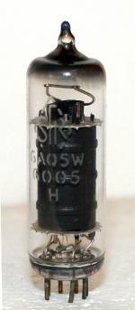
6V6 and 6AQ5 are both ROCKIN' TUBES !
'Ampex' used to use the 6AQ5 as line-driver tubes in their multitrack tape machines.
The 6AQ5 is super linear & has a GREAT sound, just like the 6V6.
I mostly know about these from guitar amps.
I have a most unusual guitar amp in fact ...
... it is the ONLY ONE that I am aware of, that actually uses the 6AQ5 as output tubes.
The 6AQ5 was just not 'fashionable' ...
... buyers either wanted typically Vox EL84, Marshall EL34, Fender 6V6 and 6L6 etc. etc.
The amp I have is a late '50s 'Selmer' made in London & it sounds AWESOME.
I would have no hesitation in recommending the 6AQ5 as a great line-driver tube.
It is probably way less microphonic than a 6V6, and was used a lot in car radios I believe.
It's a straight swap for a 6V6, so in theory you could fit parallel tube sockets & choose between both.
The 6AQ5 has always been as cheap as chips in the UK, as no one knows much about it I think.
So good quality multi-batches of NOS original tubes, are not a wallet killer.
Unlike 6V6, EL84, EL34 etc. which is millionaire territory in these parts !
It looks a bit 'dinky', but HEY it was miniaturization & a step forward from older bulky, power hungry tubes.
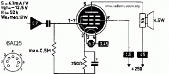
I had a look through the Thread & saw the schematic on Page 1 ...
... is there an updated one that is currently being used for builds ?
Nice Thread Salas !
Cheers.
Si.
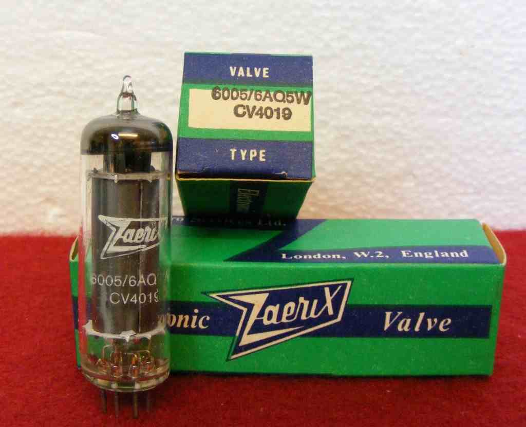
The last batch I picked up, was half a dozen of these ones.
Nice price ... nice sound !
" There has been some question about building it with the 6AQ5 in the past and I said go for it but I can't remember a build. I had also mentioned the possibility of the English 6BW6 early in the thread. I don't know if it would be subjectively identical to using a good 6V6 but it has chances to be close."
Hi filament fans
6V6 and 6AQ5 are both ROCKIN' TUBES !
'Ampex' used to use the 6AQ5 as line-driver tubes in their multitrack tape machines.
The 6AQ5 is super linear & has a GREAT sound, just like the 6V6.
I mostly know about these from guitar amps.
I have a most unusual guitar amp in fact ...
... it is the ONLY ONE that I am aware of, that actually uses the 6AQ5 as output tubes.
The 6AQ5 was just not 'fashionable' ...
... buyers either wanted typically Vox EL84, Marshall EL34, Fender 6V6 and 6L6 etc. etc.
The amp I have is a late '50s 'Selmer' made in London & it sounds AWESOME.
I would have no hesitation in recommending the 6AQ5 as a great line-driver tube.
It is probably way less microphonic than a 6V6, and was used a lot in car radios I believe.
It's a straight swap for a 6V6, so in theory you could fit parallel tube sockets & choose between both.
The 6AQ5 has always been as cheap as chips in the UK, as no one knows much about it I think.
So good quality multi-batches of NOS original tubes, are not a wallet killer.
Unlike 6V6, EL84, EL34 etc. which is millionaire territory in these parts !
It looks a bit 'dinky', but HEY it was miniaturization & a step forward from older bulky, power hungry tubes.
I had a look through the Thread & saw the schematic on Page 1 ...
... is there an updated one that is currently being used for builds ?
Nice Thread Salas !
Cheers.
Si.
The last batch I picked up, was half a dozen of these ones.
Nice price ... nice sound !
Attachments

Last edited:
Here is my version of the 6V6 preamp. I am a firm believer in low impedance drive out for any kind of preamp.
6V6 line preamp
6V6 line preamp
Nice Schematic ... Thanks !
.
Hi Nick
Nice schematic !
I see you have your heaters normal Volts, also available at 12 Volts ...
... good idea, I'm guessing that 12V6 tubes might well be a lot cheaper !
Your 'loudness' feature looks very 'practical' ...
... in all honesty, when I started using a tone-controls amp, after not having them ...
... a few dBs of bottom-end for my often lowish vol. listening is welcome !
I'm not quite sure how it works, but it seems to be linked to the attenuators level ...
... so it looks like you don't need an on/off switch, it's 'auto' depending on level ...
... neat !
Valve rectifier as well.
I bet that 317 gets a bit HOT !
I have some of the Ruskie 6SN7s coming, for hopefully a 'Valve Itch' RIAA ...
... got get slingin' that solder !
Si.
t.S.E.c
.
.
Hi Nick
Nice schematic !
I see you have your heaters normal Volts, also available at 12 Volts ...
... good idea, I'm guessing that 12V6 tubes might well be a lot cheaper !
Your 'loudness' feature looks very 'practical' ...
... in all honesty, when I started using a tone-controls amp, after not having them ...
... a few dBs of bottom-end for my often lowish vol. listening is welcome !
I'm not quite sure how it works, but it seems to be linked to the attenuators level ...
... so it looks like you don't need an on/off switch, it's 'auto' depending on level ...
... neat !
Valve rectifier as well.
I bet that 317 gets a bit HOT !
I have some of the Ruskie 6SN7s coming, for hopefully a 'Valve Itch' RIAA ...
... got get slingin' that solder !
Si.
t.S.E.c
.

Here is my version of the 6V6 preamp. I am a firm believer in low impedance drive out for any kind of preamp.
6V6 line preamp
If someone needs a nice preamp with baffle step correction this would be very easy to add the line level circuit to, just at the 6SN7 grid
I need to build one up for myself, I've built six similar (with mosfets rather than 6SN7 for the buffer) for others, but still haven't built one to keep! I've got fourteen of the Russian 6P6S on hand still, and plenty of Russian 6N8S (6SN7) too.
- Home
- Amplifiers
- Tubes / Valves
- 6V6 line preamp