DF,
Please be seated before continuing to read this.
Thanks, I thought this discussion was going so far off it was ridiculous and getting worse.
Some of the comments would have included Barlow's bit on resistance. (Lest we forget Barlow's work in his primary area still stands and is used today.)
Thanks again.
It is the driver itself that determines the current (F=BLi) that we listen to, not so much the voltage distortion of the amplifier. The current will reveal much more distortion there. If of course the amplifier produces high voltage distortion, then that will also add to the current distortion, but to a lesser degree than the driver itself.
PS: Please note for simplicity that the above example is a single driver, so that call the current of the amplifier and the driver is the same continuous current, because they are in series. So if the amplifier has a little fit on the current side, that will be added to the mix. The driver only responds to that current, as it is the sole force.
You are right, the load takes whatever current it will. So I am speaking of when it deviates from a zero current phase angle.

A deviation in the current phase angle certainly qualifies.
Does a reactive load always result in reactive current?
1. The current can only 'react' to the load in that manner with a voltage source.
2. The current does not 'react' to the load in that manner with a current source.
I am talking about equalising current, so that the current of the amplifier is the same at all frequencies.
Under those circumstances you will always have a zero degree phase angle with any drive, both voltage and current drive.
It also cancels out the output impedance of the amplifier, so that it can be any value.
But it is one thing to use EQ for termination of a filter, and it is another thing to EQ the current of the amplifier. That latter is before the filter (high or low pass) and that is what makes the amplifier's output impedance cancel out with respect to frequency response, the crossover and the box alignment.
This has the added benefit of being able to use any source Z, locks in the crossover and the bass alignment. Did you know it locks in the crossover, that was a benefit we discovered and now you can use a current source too.
What is clear is that parallel resistance works better in flattening the current phase angle:
The same improvement is heard when equalising the current of the amplifier (passive caps, inductors etc), where the EQ is on the amplifier side and not on the driver side. This is not about the terminal impedance of the driver, this is about making the current phase angle of the [single] driver go as close to zero and the amplifier produces the same current at all frequencies.
![/B]
Bob, if you're not confused you're not paying attention!
I'm not sure what you mean by "phase balancing".
Now if Joe can show that his conjugate network "predistorts" the voltage/current phase relationship in such a way that the voltage applied to the speaker voice coil is now in phase with the current through the voice coil, then I am all ears. So far he has not shown anything remotely like that.
I’m under the impression that what he’s trying to get across, it seems as though he’s saying the impedance is no longer frequency dependent?
And that the byproduct is leveled phase and a ‘locked crossover’ ?
I was surprised at the flak you (simon7000) got just from saying that not all loads are ohmic, when this is obviously (one might say trivially) true. Then I was surprised at people like PMA (who is usually correct on technical matters).
R=V/I is not Ohm's law. You need to add 'R is constant' to make it Ohm's law. An extension of Ohm's law is R=dV/dI, which is slope resistance (sometimes called AC resistance). Another extension is 'R may change, but it is not a function of I or V'. Finally, you can push it a little further if R varies only very slightly with I and V.
He is quite wrong to say that this cancels out the output impedance of the amplifier. If the output impedance is significant and either frequency or signal dependent then you will still see frequency variations or distortion caused by it.
R=V/I is not Ohm's law. You need to add 'R is constant' to make it Ohm's law. An extension of Ohm's law is R=dV/dI, which is slope resistance (sometimes called AC resistance). Another extension is 'R may change, but it is not a function of I or V'. Finally, you can push it a little further if R varies only very slightly with I and V.
It is true that the phase shift between amplifier current and amplifier voltage may be reduced by speaker impedance equalisation. The current through the speaker has not changed at all, so the sound produced by the speaker has not changed at all. I have no idea what he means by locking the crossover.mountainman bob said:And that the byproduct is leveled phase and a ‘locked crossover’ ?
He is quite wrong to say that this cancels out the output impedance of the amplifier. If the output impedance is significant and either frequency or signal dependent then you will still see frequency variations or distortion caused by it.
Yes, Joe is saying that the speaker measures constant impedance across the band of interest, IOW the loudspeaker is resistive load which means there is no stored energy to return to the energy source amplifier, this resistance/non reactive behaviour can also be expressed as load phase angle of 0 degrees.I’m under the impression that what he’s trying to get across, it seems as though he’s saying the impedance is no longer frequency dependent?
And that the byproduct is leveled phase and a ‘locked crossover’ ?
The loudspeaker input parallel local notworks that compensate/EQ the crossover/transducer reactive load characteristic also set a defined source impedance for the loudspeaker which means that the crossovers/acoustic output is invariant according to amplifier/cable resistance and frequency. This means that the loudspeaker acoustic output does not change according to the amplifier output resistance/cable resistance. The non reactive/resistance characteristic means that there is no reactive stored energy to be returned to the amplifier to cause excitation of amplifier distortion mechanisms. This is double win.....the loudspeaker does not 'upset' amplifiers which allows all amplifiers to deliver to spec and so deliver cleaner sound.
As I have said before this compensation/EQ is standard electrics and required for elimination of circulating/harmonic currents and maximum system efficiency.
Dan.
I don’t think you can ‘unstore’ magnetic energy stored in the cross over magnetic s or returned to the system via that in the speaker suspension in the manner you describe. Any stored energy will share between Joe’s damping network and the rest absorbed by the amplifier. On a big amp you will need a huge amount of energy to cause the OPS to lose control and for example to swing the output to either of the rails against its will (I am deliberately talking anthropomorphic terms here and not electrical engineering terminology).
So if it’s old hat, has anyone implemented it commercially before? Examples?
Not that I am aware of because it just doesn't make much sense.
If it’s just impedance matching or amp loading than it’s a lot of hoopla over nothing but it sure seems to me like he’s impressing more than that?
The hoopla theory is what seems closest to observation.
The problem is a lot of folks have their pet theories which don't have either any data to back them up, or worse, are in contradiction to the known world. Then there's the backfire effect when said theory gets nuked by people who know better and the emotional agenda takes foot. It doesn't take long to see the results of that especially in this thread, doubly so because Joe, not alone but more than anyone else, is dying to be taken seriously with methods that are in direct opposition to his aim.
I understand his language and he understands mine, I'm quite sure.
He used a text description of what actually happens "inside" of the formula I posted, e(t) = k*v(t) + (Ze+Zout)*i(t):
I see no point of disagreement anywhere between him and especially his explicit notion of the feedback mechanism is worthwhile because it is a key point in the amp<-->loudspeaker interface.
If otherwise, he should join the discussion personally.
So it is most probable that Joe don't understand his own EE fellows - either.
//
As Ohm's law is not a law but merely a summary of common behaviour you cannot violate it. You can either follow it (e.g. most metals) or ignore it (e.g. semiconductors).
No. Ohm's law says that for a given substance/item the current and voltage are proportional i.e. the ratio between current and voltage is a constant.
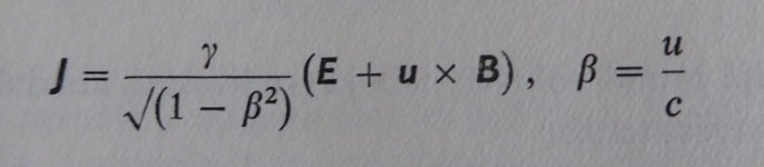
During my university years, which is really long ago (I graduated 40 years ago), we learned much wider form of the Ohm's law, than you are suggesting. To prevent incorrectness, please find it attached as a snapshot.Then I was surprised at people like PMA (who is usually correct on technical matters).
R=V/I is not Ohm's law. You need to add 'R is constant' to make it Ohm's law. An extension of Ohm's law is R=dV/dI, which is slope resistance (sometimes called AC resistance).
Attachments
Last edited:
The amplifier output/nfb senses and tracks back EMF but there is no return energy because of R's in the RC networks, ie loudspeaker is overall resistive load characteristic. This is not different to an office floor full of ballast type flouro lights....compensation caps are required inside each lamp fixture to ensure overall non-reactive load characteristic for the reasons any electrician/technician/EE should know.I don’t think you can ‘unstore’ magnetic energy stored in the cross over magnetics or returned to the system via that in the speaker suspension in the manner you describe. Any stored energy will share between Joe’s damping network and the rest absorbed by the amplifier. On a big amp you will need a huge amount of energy to cause the OPS to lose control and for example to swing the output to either of the rails against its will (I am deliberately talking anthropomorphic terms here and not electrical engineering terminology).
Last edited:
Nice try, you can't make me re-read 5 of JR's posts that easily!I’m under the impression that what he’s trying to get across, it seems as though he’s saying the impedance is no longer frequency dependent?
And that the byproduct is leveled phase and a ‘locked crossover’ ?
I don't know what "locked crossover" means. Nothing stuck in front of the driver changes the fact that the voice coil is a big fat inductor in a strong magnetic field. The magnitude of that impedance is strongly frequency dependent.
R=V/I is not Ohm's law. You need to add 'R is constant' to make it Ohm's law.
It would be easier to say that "R" needs to be expanded into a full description taking into account all functional dependencies (including time dependent ones).
For many problems this has been done, IIRC Tom Lee has a wonderful paper on noise in diode ring mixers where noise (4KTR) depends on the instantaneous diode resistance.
Best to end now, but in my observation this is always brought up in a negative spirit, i.e. the audience here are simpleton's that think a carbon comp resistor has no distortion mechanisms even at 1/2 rated power.
There are cables with RC networks to compensate loudspeaker rising impedance characteristic. Joe hinted of speakers implementing this input side impedance EQ but the manufacturers keeping quiet about it. You can try terminating your fig8 type speaker cables (100R or so) and IME this makes nice improvement in Mids/HF clarity. Joe's networks will further improve clarity and stability in the sound.So if it’s old hat, has anyone implemented it commercially before? Examples?
Dan.
So if it’s old hat, has anyone implemented it commercially before? Examples?
It would add expense and reduce performance unless the speaker happened to be connected to a valve amp. People who buy valve amps usually buy speakers to go with them.
Resistive/unity PF load means by definition no return energy/no harmonic currents/no circulating currents.....how can that not make sense ???.That doesn't and cannot make sense, Dan
no return energy/no harmonic currents/no circulating currents.....how can that not make sense
They just circulate in the shunt networks, they don't go away. Remember we are now allowed an ideal voltage amplifier not some SET amp.
- Status
- Not open for further replies.
- Home
- Member Areas
- The Lounge
- John Curl's Blowtorch preamplifier part III