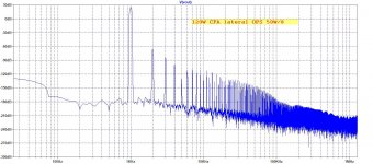
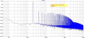
IMO, it does not make any sense to fight below 0.01% of H2 and H3 in the power amplifier. It is only a race for prestige, then, not for a better sound. On the other hand, it makes sense to keep higher order harmonics as low as possible.
This should be good enough.😀
If the real amp can get close to the simulation.
Attachments
OK, when I say EAR I mean the whole chain plus brains evaluation. Sorry I do not mean to go nit-picking in the discussion. I hate useless, nit-picking discussions without any additional value.
Yes it should be good enough IMO, if there is not another issue and if the real world fits to simulated values.
This should be good enough.😀
If the real amp can get close to the simulation.
Yes it should be good enough IMO, if there is not another issue and if the real world fits to simulated values.
Clarification is always good, don;t you think? It avoids readers who are new to this not getting the wrong impressionOK, when I say EAR I mean the whole chain plus brains evaluation. Sorry I do not mean to go nit-picking in the discussion. I hate useless, nit-picking discussions without any additional value.
yes, excellent point & not nit-picking at allToo nit-pick, the outer ear will cause distortions that don't exist at the microphone.
David Griesinger originally used in-ear microphones & found the sound recorded with these to be startlingly real. He later used an equalisation program to map the outer ear's frequency distortions for each individual. Interesting measurements of a number of individual's frequency ear mapping here
Last edited:
Because what the mic measures at a particular place is not what/how you hear the sound at the same place.
To come back to Bob's question, it's important that the spectral information in the room as a whole correlates to the direct sound in order for the brain to decipher it properly. Also at any point in space comb filtering is happening and reflections can help us fill in the gaps.
I never mentioned using a mic 😀
I was eq’ing and tweaking crossovers long before getting my imm 6 mic
It did allow me to visualize/verify what I was hearing and make life more objective......but I would never just trust a mic, in fact my lp measurements look nothing like they’re ‘supposed to’ .
Worlds in collision Joe meets Arthur Salvatore, the audio apocalypse we have all been waiting for. RECENT AUDIO NOTES
Scott, why don't you - for once in your life, stop trolling people.
Prior to this, you have dragged Charlie Hansen's name through the mud here, even after his passing. Weak as water.
Do you have any idea what the ten years or so after his bike accident would have been like?
At least Charlie, despite being in a wheelchair, had the balls to continue on at the helm of his company.
Hi Scott,
I skimmed the link you provided, it was interesting for one claim that I find improbable I'll quote that passage ...
You have got to be kidding me! Someone is giving Joe credit for Allen Wright's work!
Do either of you actually know Joe or have known Allen? Do you know their past working relationship?
You guys are way out of line and shouldn't be bringing this up here.
I know Joe pretty well, he's a man of integrity and I have met Allen many times.
I know they actually had a pretty close working relationship and that's about all I'll say here.
As I repeatedly mentioned, lowest distortion at amp output does not translate into lowest distortion sound at speaker. Seems to me that only a few designers are aware of and accept this fact. And we still have conflicting ideas on how to best exploit this fact into practical solution.Best fidelity requires sufficiently low distortion at the amp output; people still argue about how low is sufficiently low. ...
I think i hit the unsubscribe button a few months ago...Too much useless information for my monkey 🙂I guess the jokes on me, do you want it you can have it?
100 Meg Ohm of input Z of older tube mic amps is not sufficient. 3G is minimum for lowst electrical distortions. 20G Ohm is recomended in which case thd will be below .003% THD for 1/2 inch capsule used compared to 10%.
AES JUne 2000. Vol 48 No6 "Condenser microphone electrical distortions"
B&K has fundamental derivations of capsule distortion in their tech papers.
It depends what you want to achieve, but EQing at the listening position is still not a very good idea, however you do it IMHO.I never mentioned using a mic 😀
I was eq’ing and tweaking crossovers long before getting my imm 6 mic
It did allow me to visualize/verify what I was hearing and make life more objective......but I would never just trust a mic, in fact my lp measurements look nothing like they’re ‘supposed to’ .
As I repeatedly mentioned, lowest distortion at amp output does not translate into lowest distortion sound at speaker. Seems to me that only a few designers are aware of and accept this fact. And we still have conflicting ideas on how to best exploit this fact into practical solution.
And you assume you understand the issue? Do you suggest to add opposite distortion and if so, how do you handle phases of individual distortion products? Or do you suggest a current drive + DSP FR compensation? I think that speaker distortion is overestimated in this thread and other bigger issues like directivity and power response are overlooked or just not mentioned, or simply not understood. My opinion is supported by number of posts that deal with speaker nonlinear distortion, without a single attempt to understand its audibility.
As I repeatedly mentioned, lowest distortion at amp output does not translate into lowest distortion sound at speaker. Seems to me that only a few designers are aware of and accept this fact. And we still have conflicting ideas on how to best exploit this fact into practical solution.
I know this is going to get me into trouble (again): By all means have low distortion (voltage distortion) at the amplifier's output. But if you take a current sense resistor like 0.1R in the return (as long as it is in series with [single] driver. Now put a 1KHz tone through the amplifier. Look at the voltage signal and put it on the scope (CH1). Now on the 2nd channel of the scope, take the signal across 0.1R and amplify it by Re*10, where Re is typically around 6R (so 60x) for an 8 Ohm speaker. Now compare the pristine voltage signal of the amplifier (CH1) with the the current (CH2). Know that due to F=BLi the driver is reproducing CH2 and not CH1.
This is 100% pure physics, totally. This was passed by by several physicists here in Australia (one was Dr Rod Crawford) and overseas.
It gets even more interesting. By using Re*60 = x Volts, create a voltage signal (this voltage signal can be submitted to distortion test?). Measure the impedance of the drive @1KHz and using Ohm's Law calculate the current of the amplifier with x Volts and you have now calculated the heat dissipation inside the voice coil. With a microphone at 1 Metre you will see that any change in level is proportional to both current and the dissipation (within about 1% because the driver has less that 1% efficiency.
This is not mumbo-jumbo, it is the physics. If you don't understand the above, I will re-explain it so that is is perfectly understood. There would not be any here that could not understand it, as I consider you all very much capable - it's just the willingness that matters.
It is the driver itself that determines the current (F=BLi) that we listen to, not so much the voltage distortion of the amplifier. The current will reveal much more distortion there. If of course the amplifier produces high voltage distortion, then that will also add to the current distortion, but to a lesser degree than the driver itself.
Finally, the sound of the amplifier will change because some amplifiers will be able to cope better with distorted current. (I point to tubes and output transformers here as a plus and avoiding feedback from the secondary and solid state as more problematic. Certainly high feedback will mean that the amplifier will be at a greater disadvantage, especially when it transitions into Class B.)
This could well be able to explain why amplifiers do sound different, because despite the nay-sayers, they most certainly do!
PS: Please note for simplicity that the above example is a single driver, so that call the current of the amplifier and the driver is the same continuous current, because they are in series. So if the amplifier has a little fit on the current side, that will be added to the mix. The driver only responds to that current, as it is the sole force.
Last edited:
Easier than trying to read this whole thread.
Great link. Let me quote this little bit:
At the same time, Joe modified my Oppo 105D to his ultimate performance version (JLTi level 4.2 ACD "Signature"). It's hard to characterize this digital player except to say that I've never heard a dedicated CD player or digital server which comes close. I do hope you get to experience one of these - it may not reach the heights of your Upper Class A APL, but it costs about US $2,500 in upgrades to an Oppo UDP-205 or Oppo BDP-105x, so, even if you are paying the current crazy price for an Oppo 205, it's still going to cost a fraction of a 2nd hand Esoteric K-1. And with BDP-105s going for US $500, it's a truly wonderful digital player for under $3K.
It is the Joe we all know from his liberty with, and from, technical convention.
Why this quote? Because whiles ago in this thread, I remember Joe stating forcefully that he had nothing to do with that Oppo modding nonsense. But it is part of his business, apparently.
Maybe there are two different people in audio called Joe Rasmussen, but the one I have come across here has not had his integrity questioned as far as I know. His understanding of electronics has been shown to be seriously lacking, though.Terry Demol said:I know Joe pretty well, he's a man of integrity and I have met Allen many times.
No, the driver is not "reproducing" CH2. Assuming no crossovers to complicate things, the raw driving force is related to CH2. If the speaker output were simply an acoustic version of the driving current then speaker designers' lives would be much simpler.Joe Rasmussen said:Know that due to F=BLi the driver is reproducing CH2 and not CH1.
The ability of the amplifier to cope with "distorted current" is known to those who understand electronics as 'output impedance' (the lower and more linear the better). For some peculiar reason you seem to prefer those amp technologies which raise output impedance, thus making the problem worse.Finally, the sound of the amplifier will change because some amplifiers will be able to cope better with distorted current. (I point to tubes and output transformers here as a plus and avoiding feedback from the secondary and solid state as more problematic. Certainly high feedback will mean that the amplifier will be at a greater disadvantage, especially when it transitions into Class B.)
I thought we were enjoying a break from this silliness.
B&K has fundamental derivations of capsule distortion in their tech papers.
Note
There are two separate sources of distortion. The capsule design itself and the electronics. This AES is about the electronics part/interface only
RM
I am merely aware about the issue but no clear understanding yet, my measurement capability is not yet good enough. I respect your opinion and as has been stated, distortion cancellation on multiways is futile. I am exploring a possible solution within multi amp system and perhaps later current drive with FR compensation. However, an optimal solution for multiways is not necessarily the optimum for single driver or multi amp systems.And you assume you understand the issue? Do you suggest to add opposite distortion and if so, how do you handle phases of individual distortion products? Or do you suggest a current drive + DSP FR compensation?...
Joe, I'll try to understand what you are saying once somebody show measurement of distortion improvement on the actual sound due to impedance equalization you mentioned. Measurement of distortion on voltage and current have no direct consequence to the distortion of the actual sound.I know this is going to get me into trouble ...
Last edited:
😎 🙂Construction-wise, bootstrapping and guarding are used in many capsule buffers to get to the required impedance levels. The classic B&K buffer uses the leakage current of two back-to-back bootstrapped JFET diodes for buffer FET biasing, for example. Still there is a only a single digit Gigaohms feed resistor for the polarization voltage which isn't bootstrapped in the clone B&K buffer amp I own and thus this may dominate distortion. Bootstrapping can be managed on the supply side of the cable, though (haven't tried this yet)
-RNM
Last edited:
If the speaker output were simply an acoustic version of the driving current then speaker designers' lives would be much simpler.
I never said that!
The 'truth' is actually more complicated that. It is easy to simply and then criticise the simplification than actually was stated and even more so, intended.
But alas, language in brief has its limitations.
Hi Joe,
Please read this quote and tell me if it is something you have said or implied at any time, and if it is in fact true from your viewpoint.
I ask because you have described to me in the past how you were the technician that soldered things together that were Allen's designs. That is a far cry from being responsible for many of his designs!
-Chris
Please read this quote and tell me if it is something you have said or implied at any time, and if it is in fact true from your viewpoint.
Here is the context of that quotation:Joe Rasmussen was responsible for many of Allen Wright's electronic designs.
That would make you the brains of the outfit and Allen simply a figurehead. Either that, or someone is taking credit for Allen's work after his death. Who might that be?A few words about Joe Rasmussen: If you ever heard the Allen Wright Electronics valve amps of about 2 decades ago and more, (AJ Van Del Hul described his AWE Realtime power amps as the most realistic amps on earth), Joe Rasmussen was responsible for many of Allen Wright's electronic designs.
I ask because you have described to me in the past how you were the technician that soldered things together that were Allen's designs. That is a far cry from being responsible for many of his designs!
-Chris
A point worth noting wrt LF issues with measurement mics: many mics are extremely sensitive to vibration. Tapping the mic body can generate huge output transients, with both my mics (the B&K clone and an Gefell MV201). Without using a well isolated mic stand and/or elastic suspension for the mic body there is a chance that structural vibration leaks into the measurements.
- Status
- Not open for further replies.
- Home
- Member Areas
- The Lounge
- John Curl's Blowtorch preamplifier part III