Not sure who uses the term "static" , the usual suspects denote such signals as "steady-state" or "stationary" signals.")
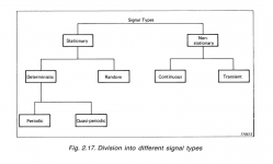
Signals are basically divided to stationary and non-stationary. If you are asking who uses the term "static", please look here where the original post is quoted
John Curl's Blowtorch preamplifier part III
however the original post disappeared since yesterday. Not only he uses this term. At least to me, "static" signal is DC.
Attachments
Last edited:
It's known as Ohm's law. We understand you are not using current drive, but you are not controlling the current in speaker either.
CORRECT!
Maybe slowly some attempt is emerging and actually trying to understand what I am saying.
And yes, Ohm's Law actually backs up what I am saying, but if only if someone will listen.
Please, go troll elsewhere.
I think it could help if you'd keep abraxalito's signature line in mind; wouldn't it be better to ask first if you did understand his posts in the way he meant it?
Just as an example, look at this post:
Are you sure you don't have me confused with @Jakob2? Just to help you distinguish better I'll point out what he frequently points out to @Syn08 - you're projecting.
His first question could mean, that he implicitly agrees (Jakob2 is playing word games) and in addition thinks that you confuse him with me.
Otoh, it could mean, that he does not agree (means, he do not think that Jakob2 is playing word games) but thinks that you confuse him with me.
Or, he didn't even intend to implicitly comment about "Jakob2's wordplay games" but just thinks that confuses him and me.
IMO no way to find out without asking......
My current signature line is there because of my taste for irony not because I want to show support for that particular style of thinkingI think it could help if you'd keep abraxalito's signature line in mind; wouldn't it be better to ask first if you did understand his posts in the way he meant it?
(Not saying you'd not realized this - as you say, impossible to tell without asking!)Well, you found a datasheet that shows it, albeit indirectly, so I will concede this point. It's literally the last AKM DAC datasheet that has an FFT plot in it, and the rest of the measurements are in the EVM pdfs.Thank you for taking the time to clarify.
This discussion (at least when I joined it after @Terry mentioned the artifact) hasn't so far been about audibility. Rather its been, all along about visibility of the artifact in the measurements. Terry said it was visible, you said you'd never seen it so I joined the fray to point to where it can be seen. Nothing has been claimed by myself, nor I believe by @Terry about whether the phenomenon is audible (or not). That's an entirely separate, but related question.
So given that you're moving the focus of discussion to 'concern' and 'audibility' can both @Terry and myself consider you now accept its visible in the measurements? If you do now accept this then my job is done in this instance.
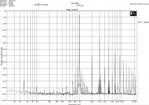
I still have some concerns as we don't exactly know that the behavior isn't the ADC in the AP? I don't know how to reconcile the fact that the FFT noise floor appears to move vs level on the AK4399 (but not 4497), yet the THD+N vs level plot is flat until what I presumed was distortion rising out of the noise. Even if it is the noise floor rising, it's still really low and only at very high input levels. AKM does not post the FFT length or window used and if they changed any of those settings.
To be fair, I did not move the discussion to audibility. It started there, and moved to a dare to even show it in the typical datasheet measurements.
Last edited:
I think it could help if you'd keep abraxalito's signature line in mind; wouldn't it be better to ask first if you did understand his posts in the way he meant it?
Just as an example, look at this post:
His first question could mean, that he implicitly agrees (Jakob2 is playing word games) and in addition thinks that you confuse him with me.
Otoh, it could mean, that he does not agree (means, he do not think that Jakob2 is playing word games) but thinks that you confuse him with me.
Or, he didn't even intend to implicitly comment about "Jakob2's wordplay games" but just thinks that confuses him and me.
IMO no way to find out without asking......
Just to satisfy your curiosity and clarify, I don't confuse you with abraxalito. He's got a lot more to offer in terms of knowledge and experience, to start. I was a little quick to jump to calling him a troll there, because it was borne out of a misunderstanding that I created.
However, I'd say you both share a linguistic or argumentative knack for something. I'm not sure how to put it into words exactly.
I still have some concerns as we don't exactly know that the behavior isn't the ADC in the AP?
That is quite possible in respect of the 'grass' in the FFTs. Even on the AK4490 you attached there's a >10dB shift between the 0dBFS and -60dBFS. I'd be much happier to trust it wasn't anything to do with the ADC if they'd used the AP's notch to dispose of the fundamental prior to digitization. Which is a point I've heard Bruno make on occasion.
You presume its distortion rising out of the noise but in my way of looking at this, the 0dBFS FFT doesn't show enough distortion to make it that. So I take it to be noise, not distortion. I'm downloading the EVM data now for the AK4490 to see if there's any commonality.I don't know how to reconcile the fact that the FFT noise floor appears to move vs level on the AK4399 (but not 4497), yet the THD+N vs level plot is flat until what I presumed was distortion rising out of the noise. AKM does not post the FFT length or window used and if they changed any of those settings.
Fair enough, I must have missed that earlier context.To be fair, I did not move the discussion to audibility. It started there, and moved to a dare to even show it in the typical datasheet measurements.
I'm not sure how to put it into words exactly.
I can have a guess at this - we both adopt the philosophy of 'don't ask, don't tell' and reckon that given enough rope a man will hang himself with it without further intervention from us
You presume its distortion rising out of the noise but in my way of looking at this, the 0dBFS FFT doesn't show enough distortion to make it that. So I take it to be noise, not distortion. I'm downloading the EVM data now for the AK4490 to see if there's any commonality.
I took another look and agree. I had edited my post but you were too quick. It's close at 0 dBFS depending on the part you look at, since the THD adds all the harmonics, but below that it's probably noise.
The THD+N vs level seems for AK4490 seems to indicate that if you listened below -10 dBFS this practically doesn't exist. Even if you listened to pop music stuck near 0 dB all day with no digital attenuation, Rob Watts is still full of it in terms of audibility.
I can have a guess at this - we both adopt the philosophy of 'don't ask, don't tell' and reckon that given enough rope a man will hang himself with it without further intervention from us
Maybe, I don't necessarily think that's it, although that could be one common "feature"
.
Last edited:
On the AK4490, I've had a look and given its much lower distortion from the FFT I'd stick my neck out and say they've solved the noise modulation issue. This from cross-checking the THD+N vs level with the 1kHz 0dBFS FFT. The grass issue on the two FFTs @1kHz I take to be the AP's ADC as its not evident on the THD+N vs level plot to that degree - the rise can be accounted for by distortion alone.
The use of an impedance flattening network at the loudspeaker gets interesting in large scale systems.
The idea is that there is resistance that is flat with frequency in the loudspeaker connection cables. If the loudspeaker impedance varies with frequency then this will result in a frequency dependent voltage divider. Thus a simple resistance results in frequency response changes in the power output. (Influenced by errors in voltage squared.)
Now in loudspeaker cables there is inductance. Not surprisingly this results in a loss of high frequency energy when the loudspeaker impedance is flat or corrected to flat. Of course the length of the cable determines if the inductance climbs high enough to affect the perceived frequency response.
A valid issue is when the cable length can make a perceivable difference. Keeping changes to well under 5% of the lowest impedance value is a typical goal. As a loudspeaker under the AES ratings may have a minimum value of 1/2 of the rated impedance that would require less than .1 ohm for the worst case of a 4 ohm rated loudspeaker. In practice that would be a 50 foot cable of ten gauge loudspeaker cable. (Wire to me means a single conductor, so that thing that connects a loudspeaker to an amplifier probably is a cable.) 16 gauge cable would be limited to 12 feet.
As loudspeaker cable generally has a characteristic impedance of 110 ohmish there may be some benefit to using a network to terminate the loudspeaker at that impedance, as the loudspeakers impedance may be much higher than that at frequencies where the characteristic impedance settles to a constant value. I suspect this cleans up much of the well out of band issues that can show up in real world systems. Problems such as RF pickup, but not sure what effect this will have on feedback settling time. (Real square wave response at the loudspeaker end of the cable.)
Back EMF is both from the resonant frequencies AND any external room noise that goes backward into the speaker. Unless you have a NATURALLY LOW IMPEDANCE, without feedback, the feedback has to generate one in order to absorb the back voltage. It does this by changing the input to create an opposite voltage. Input stages distort and can overload on such signals. IIM folks, look it up! Triodes rule!
Wow!
A. Resonant frequencies: you must mean, cone resonances? Because the cone/VC assembly itself, when at resonance, provides the easiest possible load on an amplifier, like I argued before. So, cone resonances here are vibrations in the cone that are not the basic resonance at Fb. 1) these resonances will radiate and make it a bad driver to begin with 2) only if these resonances lead to movement of the VC, they can generate a voltage. Unless you have an extremely defective speaker, see 1), this could not lead to any significant back EMF to be produced.
B. External noise going back into the speaker: have you actually measured the voltage produced by a loudspeaker as a microphone? You are talking mV's under any realistic scenario, some 3 orders of magnitude below the signal that is driving it.
How could an input stage be overwhelmed by mV size signals when it is servicing feedback measured in 10's of Volts.
See attachment below. After I posted that and the associated numbers/maths that backed up those changes in dBSPL and that it proved 1) that the dBSPL is entirely proportional to current and not voltage and 2) that the back-EMF impedance is the impedance above Re (hence total impedance is always >Re) is a real impedance.
I live in hope eternal
So you found out that if you wiggle your toes, you can see them move, but only if you look. Many before you have come to the same conclusion, Joe.
The rise you see at 3Khz and above is not the result of back-EMF but of inductance. What you can also see is that driver manufacturers aim for a straight FR under voltage drive consitions.
What do you mean by 'real impedance'?
Neither does what you mentioned Joe is NOT putting any resistance in series with the speaker. Why don't you look at Joe's schematic he has posted it.
R1 = Zls
I1 = Vamp/R1
R2 = 1/(1/Zpar + 1/Zls)
I2 = Vamp/R2
Thus: R1 > R2
Thus: I1 < I2
Vout1 = Vamp - Zamp*I1
Vout2 = Vamp - Zamp*I2
Thus: Vout1 > Vout2
This may have the same perceived effect as a added series resistor.
Mileage may vary, Zamp may be inside or outside the loop.
Last edited:
Back EMF is both from the resonant frequencies AND any external room noise that goes backward into the speaker... the feedback has to generate one in order to absorb the back voltage. It does this by changing the input to create an opposite voltage. Input stages distort and can overload on such signals.
Please see attachment by as you might find that interesting. This is thanks to Hans van Maanen who has not objected me showing it in the past, see attachment.
The source: Why do amplifiers sound different?
But my point is that the error is on the current side of the amplifier and ideally when using voltage control, you relinquish control over the current, but the only mechanism to correct is still almost universally a voltage function (feedback).
The 'resonant frequencies' you mention, they don't go away, they hang around by nature (until the music content changes or subsides). The ongoing event is causing time smear on the current side of the amplifier and the BLi (force actuated by current) means that the driver will try to faithfully reproduce that current, error and all. The BLi tells us that this is the current we end up listening to, and it is not a pretty picture.
Triodes rule!
It does look like triode/tube amplifiers are actually less problematic. At the risk of antagonising some here, is that part of the secret source?
I have now played the above scenario (SS amps) before people I consider more smart than myself and they have given it a pass. One of them is Dr. Rod Crawford who read a discussion paper I wrote (limited circulation of around twenty) and he reported back that he could not fault it. He is not the only one. Others have understood this explanation.
F = BLi always applies with dynamic drivers (linear motors) and current is the force from the amplifier, there is none other!
The rise you see at 3Khz and above is not the result of back-EMF but of inductance. What you can also see is that driver manufacturers aim for a straight FR under voltage drive consitions.
What do you mean by 'real impedance'?
"Grasshopper, you are so close and yet you do not see?"
It is part of an impedance graph and it is not an impedance? I have no words, how can you argue against an impedance plot? Could somebody please tell me what planet we are on? Or what universe?
It is not possible to understand nonsense. Saying that something is nonsense is not ridicule, it is comment.Joe Rasmussen said:If you ridicule something, then you will never understand it.
If this is indeed what he means then he has had many opportunities to say so, but he consistently tells a different story. I suspect that what you are doing is assuming that someone cannot be sufficiently ignorant to mean what Joe's words plainly mean, so therefore you assume he actually means something else.Max Headroom said:As I understand it Joe is advocating impedance eq across loudspeaker input terminals causing loudspeaker to appear as 'clean/flat' resistive load. This eliminates harmonic/circulating currents which means amplifier is not having to output harmonic currents in order to satisfy constant output voltage condition.
I have seen this phenomenon before in various settings. Someone (typically, someone respected by others) says something daft or clearly false; someone else points this out; most people then assume that they must have misunderstood him as the respected one could not possibly have meant what he clearly said.
But that is precisely where you need the "back EMF" to go in order to allow the feedback to deal with it. It would be scary if the "back EMF" somehow escaped this mechanism.john curl said:Back EMF is scary. It goes right to the input of the amp through the primary feedback resistor. IIM distortion, if you are not careful.
Oh dear!Joe Rasmussen said:that is what an impedance does, it impedes current, not voltage
And there was silly old me thinking that a voltage source is measured in volts!the back-EMF of a driver is a voltage source and can be measured in Ohm
Depending on the phase, back emf can dissipate or generate power. Only if it is purely reactive (i.e. phase is orthogonal) can it avoid real power.But the back-EMF also being a voltage source, unlike Re it does not dissipate heat
Oh dear!
I stand by it. And it is not just I who does. If somebody does no yet understand it, then so be it.
- Status
- Not open for further replies.
- Home
- Member Areas
- The Lounge
- John Curl's Blowtorch preamplifier part III