... as usual, it depends. ....
I just put another mmbt5179 50 ohm untuned amp there to terminate it. It works good at 9 and 10.7 MHz IF's - good enough to make the LM372 semi usable at 10.7 MHz; it's nominal upper limit is 2 MHz. At 455 KHz, it's not very good; maybe not enough inductance in the coil? It's wound on an FT23-43 core. Not a big deal - I think the final IF when finished will be 9 or 10.7 MHz.
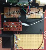
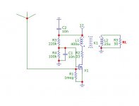
For now I've ditched the LM372 and made another temporary AM demodulator board on a piece of scrap perf. The frequency is 450 KHz using surplus four pole Murata Ceramic filters. I got 9 KC filters for fidelity, and the passband center and bandwidth look spot on, so I think I got the matching in and out about right. The IF xfmrs are 7 mm Sumida, and I verified they can tune from 450 to 460 KHz.
The amp and demodulator work well. The gain of the LM3053 is only about thirty dB as it is not using one of the transistors in the circuit. But it's stable and easy to wire. Given the cost and scarcity of genuine CA3028 / 3053 chips, there is no reason to use them today other than that I have a bunch and no need to save them as replacement parts, and if not now, then when? Sensitivity seems adequate for broadcast listening up to at least 15 MHz.
I put the schematics of the two here - if a part value is missing, I haven't decided on it or it depends.
Attachments
Oh, one other thing ...
The terrible match between the 50 ohm antenna input and my random piece of wire has been bugging me. So I wound a 49:1 unun to at least move the high impedance to a lower one and this did not work AT ALL. It was like connecting a dummy load to the input.
These are simple to wind, and I'm sure I wound it right. But it does not work at all. This is more than bugging me a little, as I have printed a case and bought some big toroid cores to make one suitable for low power transmitting, but if a little one does not work, I don't see how a bigger one will.
Any one have any ideas why, or a way to match the input, short of dragging an antenna tuner up here?
Attachments
Last edited:
No, they are not simple to wind. I rewound some M/Acom and Pulse Engineering
wideband transformers and it was a fiasco. I wanted some cheap voltage gain
for a chopper amplifier that worked into some JFETs which was a bad idea by itself
(the cheap gain).
I measured the transformers on the network analyzer, and it showed they were unusable.
For control, I rewound one core back to 1R:4R and it was somewhat worse than the original.
There must be more to it than meets the eye, like the right wire diameter and the wire twisting.
I don't think you can buy 1:49; at MCL & friends 1:16 and 1:25 are already rare.
I also was not successful in cascading transformers to get high ratios.
73, Gerhard
Last edited:
Oh, one other thing ...
The terrible match between the 50 ohm antenna input and my random piece of wire has been bugging me. So I wound a 49:1 unun to at least move the high impedance to a lower one and this did not work AT ALL. It was like connecting a dummy load to the input.
[...]
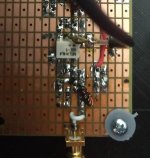
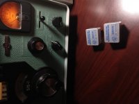
I noticed long ago that the better (and functional) way to use a short piece of wire (whip, knitting needle etc.) as antenna was to use a jfet as impedance "transformer". Back then, the proper way was to bootstrap the drain (eliminating Cgd of the fet). But with the advent of RF small signal MOS, that no longer is needed. For indoor use, a 10 min construction job, on the pic.
Attachments
... There must be more to it than meets the eye, like the right wire diameter and the wire twisting ...
There must be.
The only thing I can see I did differently from all the examples of 49:1 unun's I looked at, is that I did not twist the wires in the bifilar part of the transformer. But I never twist the wires in a bifilar or trifilar transformer - I just wind the wires on the core.
@Aridace - I had not considered an active antenna as a matching element. I suppose that could also do double duty as a variable front end attenuator by varying the voltage on gate 2 as we have seen previously.
A more pressing problem right now is AGC. My first try at it does not work at all. I have a good variable voltage corresponding to received signal strength at the collector of my detector transistor so it should be easy to turn that into a control voltage. Or so I thought ....
No signal is about 0.07 vdc and a big signal goes up to more than 0.25 vdc. The detector ( an emitter follower ) breaks up at those big signal levels around and above 0.20 vdc. I want a reverse AGC - as the detector collector voltage rises, it pulls the AGC line down.
edit: it works pretty well otherwise - good enough to go ahead and migrate the circuit to SMD on one of the prototype boards.
Last edited:
Win, an active antenna is supposed to handle fairly large signals without producing distortion. Lowering Vg2 is not a good idea. The "barefoot" MOS "transformer" as presented, at 33 mV (peak) input already produces 0.5% THD - hence short (indoor) whip. For serious work, lossless NFB is required so the NF remains low - according to simulation, with such mosfets, -183 dBV is possible even below 100 KHz.
.... an active antenna is supposed to handle fairly large signals without producing distortion. Lowering Vg2 is not a good idea. ....
Understood. I'm going to spend some time on reviewing literature and working on an AGC system, and come back to the antenna input later.
I still consider the ancient var. u pentodes among the best controllable devices for AGC. The first semiconductor devices were next to useless. That led to special RF transistors fit for gain control like BF496. But a great improvement came with symmetrical constructs, like used in the TCA440. As a complete AM chip, it can accept your 45 MHz IF and convert it to any IF lower than ~2 MHz. Take a look at datasheet TCA440
I was not familiar with that chip, but I have a similar chip already in stock, the TDA1072, and I have considered using just the IF strip and detector from it. I also have one piece of the much older RCA CA3088 that would probably also work here. Also, some LM373.
Attachments
The LM373 is intended for FM receivers, no AGC. The TDA1027A might be OK for cheap portable AM radios but its AGC range is at least 14 dB lower than that of the TCA440. In target areas with high field strength, even de 100 dB range of the TCA440 wasn't enough. The CA3088 is so bad that even at work I refused to design anything with it. Not that the TCA440 is ideal though. It will be noticed when the IF is higher than the mixer input range, the case of up-conversion: the IF amp will be swamped by the leakage from the LO. But it can be remedied by feeding the IF section from a source- or emitter follower. Apart from that, specs are "worst case". To find the location of interference I constructed an AM RX with the TCA440, wideband input, IF ~2 MHz (needing such a follower) and the sensitivity (at 20k IF bandwidth) is below 0.1 uV for "good copy". With a small active dipole it receives stations, undetectable on any car radio. People think it's FM and want to buy it ;-)
I have found what I believe is the 2.4 KHz 6 pole SSB filter to pair with the 8 pole AM filter. I have the FM filter that goes with this set ... somewhere ... I just haven't been able to find it, yet ... but I know I have it ... somewhere.
So, I think this has made the decision for me, that the second IF will be 10.7 MHz.
So, I think this weekend, if I have time, I am going to migrate the simple AM detector, and a single stage 10.7 MHz IF amp to an SMD prototype board with a 10.7 MHz monolithic crystal filter for some selectivity, as a temporary IF.
After that, I'm thinking the order of battle should be:
figure out how AGC works, at least something simple as a start
partial build out of a simple audio channel - at this point, I have a stand alone receiver, suitable for casual MW / HF broadcast listening.
Then, as time permits:
34.3 MHz crystal conversion oscillator
figure out how to mount and switch these KVG filters to minimize blowby
A real IF strip
Beat frequency oscillator
product detector
A better audio channel
synchronous AM detector
Maybe an RF amplifier
A better breadboard or case
After all that, If I'm still in the game for more pain, I'll take a stab at quad conversion so the good KVG filters can be used for passband tuning ...
Attachments
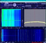
I put up a traditional shortwave reception antenna here at the lake - the 50 ft / 17 m piece of wire, with a single wire feedline at one end. The high side of it is about 50 ft / 17 m in the air, and the feedline end is about 35 ft / 11 m in the air, so it should work reasonably well once I get it matched to the 50 ohm input on the front end board...
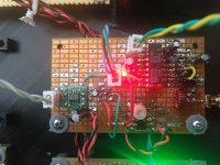
I have an LM373 IF/ Detector/AGC board built up, but it is pretty finicky about not wanting to oscillate - both at 10.7 MHz or 455 KHz, so I'm going to come back to it later as a potential sync detector.
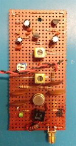
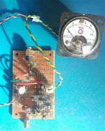
For the last week I've been using this TDA1072, although I am only using the parts of the chip after the on board mixer - the IF Strip / Detector / AGC. An added convenience is that the meter driver can directly drive the typical dirt common hamfest 0-1ma surplus meter without any pots needed to set the endpoints.
The circuit is data sheet with the exception that I used a single ended feed to the IF, instead of the balanced feed shown on the data sheet. The output impedance is pretty high, so this afternoon I added a jFET source follower to better drive that Degen thing that I am using as a powered speaker at the moment.
The pic shows WTWW pegging the AGC meter - an hour before local sunset. I've been using this board for the last week and it seems pretty satisfactory for broadcast reception. I might add another of the four pole ceramic filters to sharpen the skirts a bit more. It doesn't really need it, but I have extra filters.
I have an LM373 IF/ Detector/AGC board built up, but it is pretty finicky about not wanting to oscillate - both at 10.7 MHz or 455 KHz, so I'm going to come back to it later as a potential sync detector.
For the last week I've been using this TDA1072, although I am only using the parts of the chip after the on board mixer - the IF Strip / Detector / AGC. An added convenience is that the meter driver can directly drive the typical dirt common hamfest 0-1ma surplus meter without any pots needed to set the endpoints.
The circuit is data sheet with the exception that I used a single ended feed to the IF, instead of the balanced feed shown on the data sheet. The output impedance is pretty high, so this afternoon I added a jFET source follower to better drive that Degen thing that I am using as a powered speaker at the moment.
The pic shows WTWW pegging the AGC meter - an hour before local sunset. I've been using this board for the last week and it seems pretty satisfactory for broadcast reception. I might add another of the four pole ceramic filters to sharpen the skirts a bit more. It doesn't really need it, but I have extra filters.
Attachments
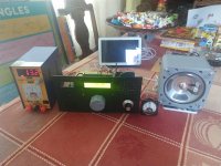
So, except for the external power supply, it is a stand alone device now, close to a pause point where I can work on better bits for it at my leisure.
I added a TDA7052A audio amp, obsolete but still readily available, cheap, as surplus. The "A" variant has the attenuator built in, which I am using instead of a traditional volume control. It can be controlled by resistance to ground, or a DC voltage. I tried it both ways and am using the DC voltage method, with an ordinary red LED to generate the reference control voltage. The data sheet says it will work at fairly high DC voltages, which is sort of true, but it doesn't work very well that way. I ran it at 14 volts and it got hot enough that I thought it would unsolder itself, although it dis not. It did not have a lot of clean output, either. At 6 volts, it works pretty well - runs tolerably cool, and easily fills the entire upper floor of the house with clean volume.
The speaker box was 3d printed from a design at thingiverse, and the driver is a 4 inch Philmore #TS45 that I got at the local radio shack.
I need to put the PIN diodes on the IF board, and remove the trim pot and replace it with a real pot on the front panel to control the attenuator.
As an alternative to the PIN diode attenuator, I am considering just putting a 50 ohm pot across the antenna input, and hooking the random wire to the slider. I've found some 16:1 transformers surplus, but haven't bought any yet. I 'm wondering if the 50 ohm pot couls serve the dual purpose of terminating the input, and still provide some attenuation when needed.
Overall, it works better than expected, pretty good actually as a casual broadcast receiver. The only flaw of consequence is the limited AGC range that is a consequence of only using the IF bit of the TDA 1072 chip.
@Gerhard:
I think I have enough gain coming out of the second IF amp to go ahead and try SDR with the RP. Since I will have IF at a single frequency, I'm thinking RadioBox might be a good starting point.
Attachments
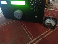
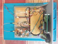
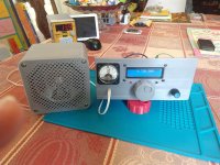
I printed a new breadboard that is smaller, puts the second IF output at the rear of the radio where it belongs, mounts the meter, ditches the front panel speaker, and ( I think ) looks like less of a dog's breakfast.
The yellow green LCD looked tacky with the grey breadboard, so I changed it to blue. I still need to print a main tuning knob in a contrasting color.
I changed the encoder from the free wheel type that I used on the SSB transceiver to a detent type since MW and SW stations are essentially channelized. When the synthesizer is set to 10 KHz steps, combined with the unexpectedly steep skirts of the 9 KHz filter at the 450 KHz second IF, stations just snap in and out of the passband. The detent tuning seems right.
Speaking of the 450 KHz second IF, on the MW BCB, there is a complete absence of beats, tweets, squeals, whistles, or other nonsense. It receives MW as well as it does SW. Which is pretty good.
With the random length longwire antenna, it hears down to the local background noise all the way to 28 MHz where it just drops off a cliff and goes completely deaf. I suspect this is an artifact of the existing non matching of the antenna input port.
I put the may or may not be PIN diodes into the IF, between the 45 MHz filter and MMBT5179 first IF amplifier. Initially I planned for them to be under manual control with a front panel pot, but after some testing and measuring, I put them into the AGC loop, using the meter drive output to control them. Preliminarily, this seems to be working well and the AGC seems to be benefitting from the extra gain in the loop. All the bits are installed to just plug in a pot and go, but it does not look like that will be needed other than to test and measure other diodes for better performance.
That left me with an extra hole in the front, so a speaker headphone jack went there.
The volume pot needs to be a linear taper, but I can't seem to find one in my junkbox with a switch. I'm not even sure if they make them.
I'm surprised at how well this radio works for such simple circuitry; I'm probably lucky that I'm here in the south central USA and the SW bands are not packed with blow torch stations like they were a couple of decades ago. That makes the task easier.
This radio is very satisfactory for broadcast listening - it will fill the entire upper floor of the lake house with clean audio and I can listen to it for hours without fatigue. I can't say that about my Drake R7, which is otherwise a superlative communications receiver, but after a few hours just starts to grate on my ears. My 51S-1 is also an exceptional fatigue free receiver, but it has a relatively narrow AM passband - this homemade radio sounds better on AM ...
Attachments
") Gerhard
Gerhard... There are not enough knobs to play with.
I know, not just not enough knobs, it also seems like not enough parts. Two transistors and an IC are all of the active RF parts. I am having a hard time getting my head around how something this simple, can work as well it does.
This is just a placeholder - should be more knobs in the future as it gets built out to a communications receiver. I hope to get RadioBox loaded up soon and start figuring out how to use the RP for SDR.
Hey. I just thought of something - this receiver is literally a kitchen table radio. I think every part of it was built on the kitchen table here at the lake. The RP made that possible - every RF hobbyist should have one of these.
... I have most of the kit for a active/tuned ferrite antenna. Now I just need the time!
Jack, I have one of the old Palomar loop bases, with a MW loop and a 75/80 meter loop that is good to 5 or 6 MHz, but I haven't used either much. It might be interesting to get it out when football season starts in a few weeks and see what it will pick up.
It works pretty well on MW with just the random wire antenna. I spent a couple of hours this morning from a little after sunrise to about 8:30 AM listening to WTAW, a 10 KW single tower station a bit more than 500 miles south of here. It was as strong as some of the 5 KW locals until it just went away.
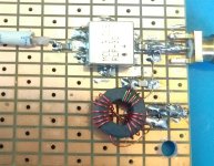
SDR has plenty of knobs, performance is adequate with exception of AGC (no "hang") and noise blanker (not capable of eliminating pulse noise generated and transmitted by the power company). Loop antennas can perform very well, this pic shows the signal from Dutch navy RTTY station (75 baud). Quite obvious it's the thunderstorm season.
Attachments
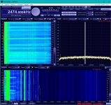
... with exception of AGC (no "hang") and noise blanker (not capable of eliminating pulse noise generated and transmitted by the power company). ...
I have some annoying noise up at the lake house. It sounds like old school point / breaker ignition spark plug noise, except it is fairly weak in amplitude ( about a 1 or 2 on the AGC meter ) is pretty broadband over 40 or 50 KHz, and occurs at what seems like random times and frequencies from MW well into the SW range. It must have a pretty hard edge on whatever it is, because when it is occurring, with the + - 4.5 KHz ceramic filter, it can still be heard on top of a much stronger AM signal. Normal background noise barely deflects the AGC meter even at MW.
The noise blanker in my FT-817 cannot silence it. It's completely ineffective. I haven't tried to lug a receiver with a better blanker up there ( my Drake R7 ). All the homes seem to be fitted with these new smart meters and I wonder if it is related to those.
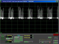
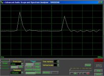
The SDR has several plugins, one of them is a scope / analyzer which I used to look at the pulses none of my radios (ICOM R71A, Drake 8B, JRC NRD-92) can blank. The pics confirm what I saw on the scope: a band of pulses synchronous with the grid frequency (60 Hz). These pulses are separated ~450 uS and the rise time is very high (limited by the 50 KHz AM filter). Clearly no existing noise blanker could eliminate that. Either I have to design a new radio with a ~ 1 MHz wide IF and noise blanker able to handle the ~450 uS pulse repetition rate, or to construct a different wideband directional antenna than the active loop which would need 3-D adjustment to eliminate the noise. Easiest is a different antenna, will be 2 active dipoles separated ~6m, with variable or just 180deg phasing.
Attachments
- Home
- Member Areas
- The Lounge
- No RF gear here?