FILES ARE AT THE BOTTOM OF THIS POST
Welcome to the 'Virtual Listening Room' which is an experiment into listening to different amplifiers in simulation. Thats right, we are going to try and listen to the 'sound' of different amplifiers using just a running simulation. The input to each amplifier is a short wave (.wav) file ripped from CD. The output of each amplifier is converted back to a wave file that can be listened to in the normal way via a PC or separate DAC etc.
Its been a bit of a journey, but a fun learning experience non the less.
The zipped folder (size22.5Mb) contains three files, one file for each different amplifier. Each file plays for 50 seconds.
The designs simulated were a vertical FET design of my own, the venerable JLH69 and an unknown (to most) and yet intriguing design from the late 70's that appeared in Practical Wireless under the 'Europa' name.
The vertical FET amp was biased at 100ma per FET pair. This amp has been designed for high current delivery and the test load impedance has been made a severe 3 ohm load for this test. This amp uses multiple rails, is 'DC' coupled and employs a DC servo for offset correction.
The JLH69 was set up for 8 ohm loading with a 1.2 amp bias. Rail voltage as at 27v. This is a single rail AC coupled design.
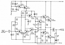
The Europa was also set for 8 ohms and with a 25ma bias current. The Europa uses two 2N3055's for the output stage in a quasi arrangement. Rail voltage is 56 volts DC. This is also an AC coupled single rail design.
I found that the amplifiers could be simulated either in stereo by duplicating the circuit on the spice workspace and then running the simulation as one entity or, simulated for left and right channels separately with the two wave files being made into a stereo track using Audacity.
If you get chance to give these a listen (and I hope you will) then I'll later post the file of the direct ripped test track excerpt.
Have fun, I know I did 😉
Having the files on Dropbox means you do not need install anything. Just let the page load (it takes several seconds for the download link to the files to appear).
AMPLIFIER FILES
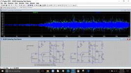
This picture gives a clue as to what we are listening to. This shows the JLH set up for a stereo listening session with capture of both channels.
There is also a poll added to the top of this post.
Welcome to the 'Virtual Listening Room' which is an experiment into listening to different amplifiers in simulation. Thats right, we are going to try and listen to the 'sound' of different amplifiers using just a running simulation. The input to each amplifier is a short wave (.wav) file ripped from CD. The output of each amplifier is converted back to a wave file that can be listened to in the normal way via a PC or separate DAC etc.
Its been a bit of a journey, but a fun learning experience non the less.
The zipped folder (size22.5Mb) contains three files, one file for each different amplifier. Each file plays for 50 seconds.
The designs simulated were a vertical FET design of my own, the venerable JLH69 and an unknown (to most) and yet intriguing design from the late 70's that appeared in Practical Wireless under the 'Europa' name.
The vertical FET amp was biased at 100ma per FET pair. This amp has been designed for high current delivery and the test load impedance has been made a severe 3 ohm load for this test. This amp uses multiple rails, is 'DC' coupled and employs a DC servo for offset correction.
The JLH69 was set up for 8 ohm loading with a 1.2 amp bias. Rail voltage as at 27v. This is a single rail AC coupled design.
The Europa was also set for 8 ohms and with a 25ma bias current. The Europa uses two 2N3055's for the output stage in a quasi arrangement. Rail voltage is 56 volts DC. This is also an AC coupled single rail design.
I found that the amplifiers could be simulated either in stereo by duplicating the circuit on the spice workspace and then running the simulation as one entity or, simulated for left and right channels separately with the two wave files being made into a stereo track using Audacity.
If you get chance to give these a listen (and I hope you will) then I'll later post the file of the direct ripped test track excerpt.
Have fun, I know I did 😉
Having the files on Dropbox means you do not need install anything. Just let the page load (it takes several seconds for the download link to the files to appear).
AMPLIFIER FILES
This picture gives a clue as to what we are listening to. This shows the JLH set up for a stereo listening session with capture of both channels.
There is also a poll added to the top of this post.
Attachments
Did you have to do anything to "normalize" the output WAV files? One place I read about this process mentioned that LTspice may "panic" when the output exceeds 1V. Based on your screen capture, I am guessing not... But, thought I would ask.
This is definitely something I must try with my own circuits. How long did the simulations take?
EDIT: Are we to send you conjectures about which amp corresponds to which clip, or are they simply in the order you listed?
This is definitely something I must try with my own circuits. How long did the simulations take?
EDIT: Are we to send you conjectures about which amp corresponds to which clip, or are they simply in the order you listed?
Last edited:
Europa was published in Practical Wireless, 1978, March and this issue can be downloaded from:
PRACTICAL WIRELESS: British Electronics and Hobbyist Magazine
I couldn't see anything 'intriguing' in this design, but I can be wrong.
With regards sound files, listening may be fun, but IMHO this is the sound of particular models, not the amplifiers
PRACTICAL WIRELESS: British Electronics and Hobbyist Magazine
I couldn't see anything 'intriguing' in this design, but I can be wrong.
With regards sound files, listening may be fun, but IMHO this is the sound of particular models, not the amplifiers
Attachments
Tried them! Long time since I heard "fun,love and money". As i seem to be the first i won't say nuffink yet.
Did you have to do anything to "normalize" the output WAV files? One place I read about this process mentioned that LTspice may "panic" when the output exceeds 1V. Based on your screen capture, I am guessing not... But, thought I would ask.
This is definitely something I must try with my own circuits. How long did the simulations take?
EDIT: Are we to send you conjectures about which amp corresponds to which clip, or are they simply in the order you listed?
I ran the simulations on a Dell laptop that has 4Gb RAM and an SSD. They didn't take too long per run, perhaps 10 to 15 minutes for the Europa and JLH. My amp is considerably more complex in design and that took longer.
For the levels, I looked at how the ripped track looked in Audacity with regard to peaks. The JLH with its 27 volt rail was the 'lowest denominator' and so that set the initial levels.
I then rigged up an attenuation network at the output such that the output of a test 1kHz tone had the same amplitude as the input. That step was done for the other two amps.
The order of the amp files is random and may or may not be in the order they get mentioned.
Please (everyone) pots your comment in the thread. It all makes for interesting reading.
Tried them! Long time since I heard "fun,love and money". As i seem to be the first i won't say nuffink yet.
Please do. All comments welcome.
I couldn't see anything 'intriguing' in this design, but I can be wrong.
I find the input stage intriguing as it uses a darlington arrangement on the inverting side. The VAS being PNP also allows the speaker coupling cap to have a dual function of bootstrapping the lower driver. Feedback component values are unusual too. Very high resistance values and very small return cap (I think it was a tant in the original).
No emitter resistors meant the biasing was definitely knife edge and I had problems with thermal runaway despite using a large heatsink and having the vbe multiplier clamped to it. It was all valuable learning though, and I have fond memories of how it sounded back in the day although the integrated preamp using an LM381AN was the worst ever.
Well spotted. Yes it is drawn incorrectly as an NPN rather than a PNP. They used to publish corrections in PW but I can't recall if that error ever got pointed out.
With regards sound files, listening may be fun, but IMHO this is the sound of particular models, not the amplifiers
Keep thinking about this.
I'm not sure that I fully agree on that point, for example a really simple simulation of a one transistor amp that generates lots of even harmonic distortion... what are we listening to ? The circuit and its distortion profile, or the models ?
Surely it has to be the circuit. The real build would sound essentially the same no matter what (suitable) transistor was used. Why not the simulation. Where it perhaps gets interesting is as the distortion profile becomes smaller in magnitude.
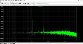
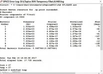
These are distortion figures and FFT plots for the Europa, The FET amp and the JLH respectively. Level playing field at 8 ohms for all.
Attachments

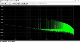

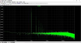
Interesting, Mooly. From looking at the Fft and that you use vfet, the chance is small that your fet amp is not the best sounding one. The fft shows a class A characteristics. It must be ccs loaded instead of bootstrap like jlh. But jlh is designed to have unconditional stability without compensation. Your amp should use cap compensation to achieve similar stability. How you do it is the remaining variable.
Had a quick look at the schematic - are you really using a pure voltage source for the power supply? If so I reckon they should sound perfect as in my experience its the PSU which gives the amp its sound 😀
Thanks for looking at these.
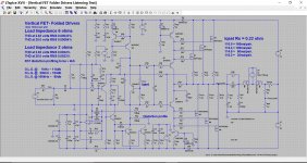
It is quite a complex amp, the circuit is below.
Yes they are all pure DC voltages and I agree it could be interesting to try this with real rails that include ripple and that also have a bit of impedance.
I thought afterwards that using a more complex load might have been a better idea to. Wonder how all that would affect simulation times.
That said, we are happy to simulate designs using the methods here, and then take those designs to a real build so its perhaps a fair starting point.
I've had a comment via pm saying that one of three definitely sounds inferior to the other two. But which one 😉
Interesting, Mooly. From looking at the Fft and that you use vfet, the chance is small that your fet amp is not the best sounding one. The fft shows a class A characteristics. It must be ccs loaded instead of bootstrap like jlh. But jlh is designed to have unconditional stability without compensation. Your amp should use cap compensation to achieve similar stability. How you do it is the remaining variable.
It is quite a complex amp, the circuit is below.
Had a quick look at the schematic - are you really using a pure voltage source for the power supply? If so I reckon they should sound perfect as in my experience its the PSU which gives the amp its sound 😀
Yes they are all pure DC voltages and I agree it could be interesting to try this with real rails that include ripple and that also have a bit of impedance.
I thought afterwards that using a more complex load might have been a better idea to. Wonder how all that would affect simulation times.
That said, we are happy to simulate designs using the methods here, and then take those designs to a real build so its perhaps a fair starting point.
I've had a comment via pm saying that one of three definitely sounds inferior to the other two. But which one 😉
Attachments
I just realized what this is all about. A virtual amplifier. Interesting idea and im urious how it would correlate with reality 🙂
- Status
- Not open for further replies.
- Home
- Member Areas
- The Lounge
- Welcome to the (virtual) listening room.