Are they really damn! I bought the toroidal already. Hopefully I can use it on something else.Now it seems that the Relays are obsolete... I'm seriously giving up on this one.
Now it seems that the Relays are obsolete... I'm seriously giving up on this one.

Mouser has 2.582 KEMET/NEC EA2-12NJ or 3.298 EA2-12NU relays able to dispatch immediately. DigiKey has 4.257. The Fujitsu/Takamisawa A-12W-K is again stocked in the thousands. All those are listed as interchangeable in the BOM and carried also by RS Element14 SOS TME etc.
Well done Salas. I checked a few weeks ago and seen the kemet also.
Mouser has 2.582 KEMET/NEC EA2-12NJ or 3.298 EA2-12NU relays able to dispatch immediately. DigiKey has 4.257. The Fujitsu/Takamisawa A-12W-K is again stocked in the thousands. All those are listed as interchangeable in the BOM and carried also by RS Element14 SOS TME etc.
Cheers
Orange ones* glow as nicely and in stock so the red LEDs saboteur failed to stop us.
*WP2773ND
Salas. I contacted the manufacturer and they recommended these:
WP144IDT
Will they work as well? It appears to just be a different shape (from all I can tell).
LED Indicator Power Button
All. I'm wanting to add a switch with a blue LED power indicator {this is a Pass design after all }. It looks like I can find one that requires a 12V power source. Can I tap into the Mezmerize board someone and pull the 12V to have the 12V power source when powered up? I'm looking at possibly one of these three:
I'm new, so please forgive me. But it looks like there's a 10V source after C2 (according to the schematic). Can I pull the positive off of there and ground it on the otherside of C2? Or is there somewhere else more convenient and/or available?
Is the 10V enough or can I get 12V somewhere else? Seems like 12V might exist somewhere since I'm coming from a 15V transformer. Maybe somewhere around the 12V regulators?
Also, will I need a resistor? It looks like, according to the switch schematics, that only the TE switch has an inline resistor, so will I need to add one if I go with one of the other two options? If so, just calculate it off the max current for the LED and my supply voltage?
Also, I believe I'll meet the current and power requirements (since I'll be switching 120VAC; I just used the recommended 1.25A fuse as a guide), but if anyone can verify I'd greatly appreciate it.
Lastly, does anyone recommend any of the brands over the other? What about any other options/possibilities?
Thanks!
All. I'm wanting to add a switch with a blue LED power indicator {this is a Pass design after all
}. It looks like I can find one that requires a 12V power source. Can I tap into the Mezmerize board someone and pull the 12V to have the 12V power source when powered up? I'm looking at possibly one of these three:- EAO 82-5151.2123 (https://www.mouser.com/ProductDetail/123-82-5151.2123 and https://eao.com/fileadmin/documents/PDFs/en_us/03_brochures/EAO_PB_82_Pushbutton_US.pdf)
- E-switch ULV4F23SS344 (https://www.mouser.com/ProductDetail/612-ULV4F23SS344 and https://www.e-switch.com/system/asset/product_line/data_sheet/207/ULV4.pdf)
- TE Connectivity AV1921P712Q04 (https://www.mouser.com/ProductDetail/506-AV1921P712Q04 and https://www.te.com/commerce/Documen...pdfEnglishENG_CD_2213766_B.pdf7-2213766-7)
I'm new, so please forgive me. But it looks like there's a 10V source after C2 (according to the schematic). Can I pull the positive off of there and ground it on the otherside of C2? Or is there somewhere else more convenient and/or available?
Is the 10V enough or can I get 12V somewhere else? Seems like 12V might exist somewhere since I'm coming from a 15V transformer. Maybe somewhere around the 12V regulators?
Also, will I need a resistor? It looks like, according to the switch schematics, that only the TE switch has an inline resistor, so will I need to add one if I go with one of the other two options? If so, just calculate it off the max current for the LED and my supply voltage?
Also, I believe I'll meet the current and power requirements (since I'll be switching 120VAC; I just used the recommended 1.25A fuse as a guide), but if anyone can verify I'd greatly appreciate it.
Lastly, does anyone recommend any of the brands over the other? What about any other options/possibilities?
Thanks!
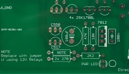
The PWR LED pads on the Mezmerize board* provide for a power indicator LED. There, a 12V source (LM7812) outputs through a 2.2K resistor on the circular anode pad and the square one is ground for cathode. You can either alter the resistor's value for different brightness or use a link instead when there's a resistor in the switch for its LED already.
*Image crop showing the PWR LED area from the Ten Years After Mezmerize special edition board prototype. The production one as available on the DIYA shop is blue with gold pads and thick copper.
*Image crop showing the PWR LED area from the Ten Years After Mezmerize special edition board prototype. The production one as available on the DIYA shop is blue with gold pads and thick copper.
Attachments
Thanks @Salas for pointing that out. The actual procuction board doesn't have such designation (and even looking now I can't find where VDD is specified).
Any thoughts on these alternative LEDs?
Lastly. I have both quad matched 2SK170B and LSK170B, any thoughts on which would sound better? Linear Systems claims lower noise than the Toshiba's, but I'm not sure about SQ. Either way, I'll be putting 6 unmatched LSKs in the power section; I'm assuming mixing (power and audio sections) is permissible, as long as each section matches.
Any thoughts on these alternative LEDs?
Salas. I contacted the manufacturer and they recommended these:
WP144IDT
Will they work as well? It appears to just be a different shape (from all I can tell).
Lastly. I have both quad matched 2SK170B and LSK170B, any thoughts on which would sound better? Linear Systems claims lower noise than the Toshiba's, but I'm not sure about SQ. Either way, I'll be putting 6 unmatched LSKs in the power section; I'm assuming mixing (power and audio sections) is permissible, as long as each section matches.
Sorry, the edit button doesn't seem to work from my phone (was going to tag this on at the end of my last post), but what options are there for adding a second output? Do I just run it in parallel with the first? Will that affect the SQ or output impedance (both if I'm only utilizing one connected device or even using both simultaneously)? Or do I need to use a selector or something else to do it properly?
1. Does your board have "Ten Years After" printed on it but it does not have the PWR LED designation? Maybe its one you bought before the TYA issue? In any case it should have a 2.2K resistor and one LED at the same places.
2. The WP144IDT manufacturer recommended replacement looks good. It has identical parameters to WP2273ID. The difference is only cosmetic i.e. its top corners are not curved as in the WP2273ID.
3. I am not sure if there can be any detectable differences between the Toshiba and the Linear Systems, especially in unity gain as used here. Prefer the quad in which there are units to be found closer together per pair for IDSS in my opinion.
Those quads % spec could have been originally different also. For example in a power amplifier's input pair there could be 1mA tolerance target to declare a match but in DCB1's direct coupled CCSed source follower circuitry 0.1mA-0.2mA spec for excellent DC offset. You should always verify tolerances when buying matched semiconductors anyway.
4. You should "buffer" a tapped off secondary output with a 100 Ohm high quality resistor in series with each one of its RCA chassis connector's center contact.
1. Does your board have "Ten Years After" printed on it but it does not have the PWR LED designation? Maybe its one you bought before the TYA issue? In any case it should have a 2.2K resistor and one LED at the same places.
2. The WP144IDT manufacturer recommended replacement looks good. It has identical parameters to WP2273ID. The difference is only cosmetic i.e. its top corners are not curved as in the WP2273ID.
3. I am not sure if there can be any detectable differences between the Toshiba and the Linear Systems, especially in unity gain as used here. Prefer the quad in which there are units to be found closer together per pair for IDSS in my opinion.
Those quads % spec could have been originally different also. For example in a power amplifier's input pair there could be 1mA tolerance target to declare a match but in DCB1's direct coupled CCSed source follower circuitry 0.1mA-0.2mA spec for excellent DC offset. You should always verify tolerances when buying matched semiconductors anyway.
4. You should "buffer" a tapped off secondary output with a 100 Ohm high quality resistor in series with each one of its RCA chassis connector's center contact.
- Sorry, *please* forgive me. I looked over the board when I received it and it looked identical to the board shot on the DIY store. They are close, but there are subtle differences; so mine does have the power LED designation like your attached picture does (when the store picture doesn't).
- Great news on the LEDs. I'll go for those as red is less flashy/bright.
- Thanks for the tip. I'm either deciding between himmel_shop (Himmel means sky or heaven in German for those that are curious)on eBay or Boozhoud Labs (BHL, website or Amazon: https://www.amazon.com/dp/B07C9XDJ83/). Himmel_shop doesn't mention tolerances, but I saw that you recommended him in previous posts. BHL mentions within 0.1mA matching by hand.
- Am I only buffering the secondary/tapped output? So I'll need two (2x) 100-Ohm resistors (i.e., one for each channel's hot). I'm not very familiar with good audio resistors other than a recommendation I've seen from another project: Vishay MRA series (Vishay - Resistors, Fixed - MRA - Wirewound Resistors, Non-Magnetic, Non-Inductive, Axial Lead), but they are rather large 4-12 Watts and expensive. Any brand + series and power suggestions here would be greatly appreciated.
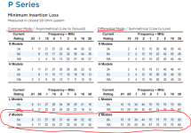
- Sorry last/new question: Would a filtered power inlet provide any benefit? TE Connectivity's P Series Z Models appear to offer some benefits at least down to 10kHz. See attached. If it's not worth the trouble or cost(!), I'll stick with a Schurter non-switched fused inlet.
Thanks a lot for the help!
Attachments
I got myself about half-way through stuffing the PCB about 5 years ago and picking this up again. But I never understood from the build threads, how are the matched pairs arranged?
From left to right, there are 4 locations for the JFETs in the signal path -- the photo has my 2 matched pairs above the board. Are the matched pairs kept together per signal channel? In other words, from left to right, would on use #1 from 8.84, #2 from 8.84, #1 from 8.94, #2 from 8.94? Or #1 from 8.84, #1 from 8.94, #2 from 8.84, #2 from 8.94?
Apologies if that isn't clear.
I don't know the answer to your question so it will be a guess. Match the pairs as in your first option, they are all very close anyway so it may not matter? Hopefully Salas will be along to tell you.
My preamp is finished. I am listening now and very good it is too. Lacks some dynamics and weight compared to a setup costing twenty times more, but no surprise, still nice sound and a totally different presentation. Very strong on quietness, stereo image, placement and channel separation. I don't know why or even what these terms really mean! Looks great in its Naim shoe-box.
Dropbox - Finmez1.JPG
Dropbox - Finmez3.JPG
Really enjoyed this build, thanks.
Last edited:
- Sorry, *please* forgive me. I looked over the board when I received it and it looked identical to the board shot on the DIY store. They are close, but there are subtle differences; so mine does have the power LED designation like your attached picture does (when the store picture doesn't).
- Great news on the LEDs. I'll go for those as red is less flashy/bright.
- Thanks for the tip. I'm either deciding between himmel_shop (Himmel means sky or heaven in German for those that are curious)on eBay or Boozhou
- Am I only buffering the secondary/tapped output? So I'll need two (2x) 100-Ohm resistors (i.e., one for each channel's hot). I'm not very familiar with good audio resistors other than a recommendation I've seen from another project: Vishay MRA series (Vishay - Resistors, Fixed - MRA - Wirewound Resistors, Non-Magnetic, Non-Inductive, Axial Lead), but they are rather large 4-12 Watts and expensive. Any brand + series and power suggestions here would be greatly appreciated.
- Sorry last/new question: Would a filtered power inlet provide any benefit? TE Connectivity's P Series Z Models appear to offer some benefits at least down to 10kHz. See attached. If it's not worth the trouble or cost(!), I'll stick with a Schurter non-switched fused inlet.
Thanks a lot for the help!
4. Yes only use them at the secondary output. Use something like a Vishay CMF50100R00FHEB
5. Its not a very susceptible circuit due to no voltage gain and line level operation. The majority of its builders did not show mains filters used but such extras even when there's no specific polluted power source problem to address they are not harmful either.
From left to right, there are 4 locations for the JFETs in the signal path -- the photo has my 2 matched pairs above the board. Are the matched pairs kept together per signal channel? In other words, from left to right, would on use #1 from 8.84, #2 from 8.84, #1 from 8.94, #2 from 8.94?
Exactly right
My preamp is finished. I am listening now and very good it is too. Lacks some dynamics and weight compared to a setup costing twenty times more, but no surprise, still nice sound and a totally different presentation. Very strong on quietness, stereo image, placement and channel separation. I don't know why or even what these terms really mean! Looks great in its Naim shoe-box.
Dropbox - Finmez1.JPG
Dropbox - Finmez3.JPG
Really enjoyed this build, thanks.
Congratulations. Does the expensive setup use a preamp with voltage gain by the way?
Yes Salas I think it does, a Naim 52 Supercap. Your B1 Buffer Preamp seems to have less gain in comparison, but a "more satisfying" presentation. Just different in a way that is good to live with. Currently using a lower grade single Exposure power amp because it has the Velleman DC protection fitted. Might try the full active power amp setup if I am feeling brave in a day or two.
I am putting together the Mouser order for the Mesmerize, and I want to avoid confusion.
I amusing the pdf titled "Mez_TYA_018_BOM_Notes.pdf" and I do have a 10trs after board.
After going through the 2 other threads here, and the build thread at Audiocircle
DC-Coupled B1 Buffer Build
It seems that "hottrodding" is a good idea.
If I am reading the BOM correctly, it seems that the 4x 18R Rset resistors are for the "medium" hottrod at about 200mA.
Is this correct?
It mentions in the DCB1 BOM, and in other places that the mur120's should be replaced with mur840's.
Am I right in thinking this should only be done if I try to push the power up higher? There is a reasonable chance I will have to use a case fan on this build (it will also have the Allo Katana stack with 4 more power supplies. So, I figure if I have to resort to case cooling, I might as well push up the power on the Mesmerize. I plan to leave it as designed for the moment though.
Also,
The Alps pots are pretty much unobtainium in the US it seems from reputable dealers.
Plenty of them on Ebay, made in Japan - ships from China...
Mouser sells 100K ones, they list exactly 1 10K pot, but it is really a 100K according to the spec sheet.
I ordered what may be a fake from a US seller. Will let every one know what it looks like it gets here.
Heavy hot-rod with big sinks, and air cooling aid even, was meant for the Hypnotize board which had boosted rectification and reservoir filtering section but no on-board input selector section.
With 4X18R i.e. 9R per side, because those are parallel pairs, you get medium hot-rod and an overall manageable thermal dissipation. Up to that point the MUR120s should serve well (allow a couple of mm distance between their body and the board for air circulation). Its a rather max point for the Mezmerize board considering the whole assortment of its parts for the sound quality gain and the diminishing returns after a point.
Element14 (Farnell) or RS Components for Alps 20K Log:
E14 Order Code: 1191722
RS Stock No. 263-3258
Element14 (Farnell) or RS Components for Alps 20K Log:
E14 Order Code: 1191722
RS Stock No. 263-3258
Farnell is back order for international, and their site always breaks on me at check out. I gave up on them years ago.
RS for USA or Canada does not even list Alps potentiometers, and has no shipping options for the overseas options I tried.
I think maybe the best thing is to replace the pot with a header. This will give me more flexibility for board placement, and let me swap different pots in and out.
Any special considerations for the wire? I have some shielded 8 conductor 18ga twisted signal wire I used when I added speed control, tach, etc to my 3phase lathe.
I could also chop up a HDMI cable for some better wire.
Thanks
-Josh
- Home
- The diyAudio Store
- Mezmerize B1 Buffer Preamp