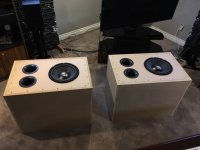
I have been using two of these vented 6.5 cu. ft. subs with my stereo/home theatre system since 2000. While they have been re-aligned since then, they are big and they are not pretty. I plan to repurpose these 'classic' drivers in a servo-feedback design or die trying. ")
Attachments
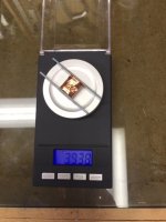
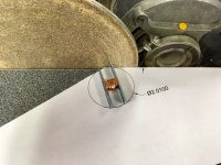
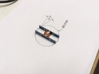
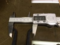
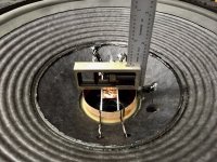
The accelerometer mounting legs need to be trimmed to fit in the voice coil former. Here the inside diameter is measured and transferred to an AutoCAD sketch so the amount of material to be removed and the optimum angle is determined. This is used as a guide to trimming on a disk sander.
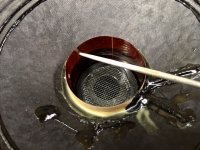
The accelerometer is test fit a few times and trimming stops when it is a loose, sliding fit in the voice coil former.
The accelerometer is test fit a few times and trimming stops when it is a loose, sliding fit in the voice coil former.
Attachments
Last edited:
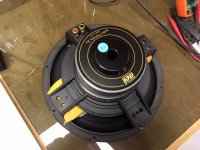
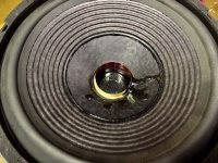
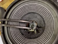
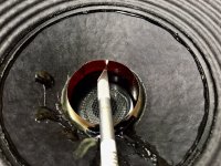
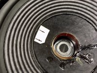
The voice coil former on this driver sits high so holes were cut for the wires for the accelerometer leads to pass through. The locations were marked, the former pierced with a hobby knife and the holes brought to their final size with a needle file.
Attachments
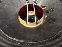
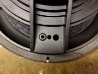
There is a suitable mounting location for the accelerometer lead termination board opposite the voice coil terminations. It is quite far from the centre so the accelerometer leads will be brought up along the outside of the cone first like the main voice coil wires. The pass-thru hole locations were marked on masking tape.
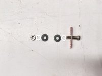
The termination mounting location already has some holes and it will be easier to mount the board on the outside rather than the inside of a cast basket arm. As luck would have it, I had just the right size grommets to insulate the holes through which the wires would pass. The hardware set shown was used to mount the termination plate. Insulated step washers isolate the board from the cast frame.
The termination mounting location already has some holes and it will be easier to mount the board on the outside rather than the inside of a cast basket arm. As luck would have it, I had just the right size grommets to insulate the holes through which the wires would pass. The hardware set shown was used to mount the termination plate. Insulated step washers isolate the board from the cast frame.
Attachments
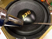
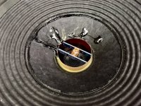
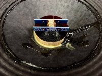
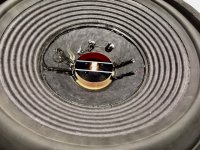
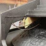
The leads are soldered to the accelerometer and passed through the voice coil former and through the holes in the cone. This cone is very think and a small drill was used in lieu of a sharp puncturing tool. The wires are coaxed to lay flat on the cone and the accelerometer squared up prior to gluing in place with MG Chemicals "Speaker Service Cement". The cement is used to secure the accelerometer leads to the cone surface to match the voice coil leads.
Attachments

Last edited:
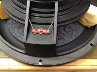
The leads are glued on the underside much like the voice coil leads on the other side and the wires pulled through the termination board until wire strain with maximum excursion is kept low but without too much slack.
This completes the accelerometer installation. Next the development board...
This completes the accelerometer installation. Next the development board...
Attachments
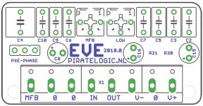
To go with the accelerometer, PirateLogic sells the EVE servo evaluation kit. This is a small PCB with a mix of analog surface mount and through-hole components that sums the signal from a preamplifier and from a conditioned feedback signal from the accelerometer sensing voice coil motion and sends this to the amplifier. Some of the passive components need to be selected based on the characteristics of the driver to increase the amount of feedback correction that can be applied before instability occurs.
Attachments
Before looking at customizing the board components for the ACI SV12 driver, a bit of background to consider:
Physics
Some key items to note regarding the physics of a speaker system to be controlled with negative feedback:
Like any spring-mass system, the response of a speaker in a closed box transitions from a compliance dependant region F = kx) to a mass controlled region (F = ma) as it passes though Fsc. As such, its response is much like a second order high pass filter with the corresponding 12 dB/Oct slope and 180º phase shift. The force F is proportional to the current in the voice coil. It can be shown mathematically that the 12 dB/Oct slope is a direct consequence of the amplitude becoming a constant regardless of frequency below Fsc where F = kx.
It can be demonstrated with mathematical analysis that the RMS pressure generated by the loudspeaker diaphragm is linearly proportional to the RMS acceleration of the diaphragm. This allows acceleration to be used as the feedback signal to control amplitude and in the mass controlled region and by virtue of the equation of motion it will be in phase with the current driving the loudspeaker.
The equation of motion is mx"+rx'+kx=F where x”, x’ and x are acceleration, velocity and displacement respectively, m is the moving mass, r is the damping constant, k is the spring constant and F is the force exerted on the moving mass.
Negative feedback decreases the total Force on the moving mass. For example, with acceleration feedback, the equation of motion becomes mx” + rx^'+ kx = F – m^' x” where m’ represents the feedback term which is proportional to acceleration. Rearranging, it is shown there is an increase in “apparent effective mass” (m+m^')x" + rx' + kx = F. In other words, the loudspeaker diaphragm will act as if it is much heavier. This will reduce the resonant frequency and increase Q.
Similarly, velocity feedback increases the damping term reducing the Q value and displacement feedback increases the stiffness term increasing the resonant frequency and the Q value.
Acceleration feedback is inertial (no stationary reference required) making it the best representation of the actual sound the loudspeaker diaphragm will produce all else being equal.
Audibility of low frequency distortion:
The Fletcher Munson curve illustrates that the human ear is relatively insensitive to lower frequencies – particularly at low sound pressure levels. Loudspeaker diaphragm excursions become very large at low frequencies and greater harmonic distortion is produced due to mechanical and electromagnetic non-linearities associated with large excursions at these low frequencies. The non-linearities produce relatively high amounts of particularly troublesome (non-musical) odd-order distortion.
The two conditions described above combine to make the reduction of low frequency distortion particularly beneficial to making audible improvements to fidelity. For example, without feedback, a loudspeaker trying to reproduce a pure 20 Hz tone at a certain SPL may produce a healthy amount of 3rd harmonic distortion. The human ear is much more sensitive to this 60 Hz harmonic than it is to the 20 Hz fundamental. When motional feedback reduces the level of the 60 Hz harmonic by say, 15 dB, the difference in the tonal character at the same SPL is clearly audible. And as predicted by the Fletcher Munson curves, the perceived loudness of the corrected signal is clearly lower due to the lack of harmonic content – which shouldn’t be heard anyways.
It follows from the above that it is best to maximize negative feedback at frequencies where distortion products will occur. Little or no feedback is required at the fundamental frequencies. For example, if low distortion is desired at 25 Hz, the amount of feedback in the region of the 2nd order harmonic 50 Hz and especially the 3rd order harmonic 75 Hz should be high.
What volume should the used for the closed box when using MFB? A small box pushing the Q above 1 can be used since the response should be smoothed and extended downward by applying feedback. But smaller enclosures will require the amplifier to work harder to develop more current to produce larger forces on the voice coil at lower frequencies to maintain sound pressure level. Another consideration is a bit of a bump in frequency response as produced by a higher Q system can be beneficial if it increases the amount of feedback in a region where harmonics are likely to occur.
The original specifications for the ACI SV12 driver are shown below. This data was used in WinISD to model the predicted LF response of the driver. As a compromise and to make the enclosures compact enough for the intended purpose as a base for a stereo pair of existing two-way speakers, a volume of 1.75 cu ft was selected producing a Q of 0.94.
The original specifications for the ACI SV12 driver are shown below. This data was used in WinISD to model the predicted LF response of the driver. As a compromise and to make the enclosures compact enough for the intended purpose as a base for a stereo pair of existing two-way speakers, a volume of 1.75 cu ft was selected producing a Q of 0.94.
Attachments
Nice work. One thing: the litz wires seem to be a bit short, which might cause excessive bending and cause them to fail.
Thanks. Frankly I'm not sure if the braided "tinsel" wires should be longer or shorter. The wires run up to the top of the frame casting so are probably an inch (2.5 cm) longer than can be seen in the photo. I had them longer at first but it appeared they might "slap" against the back of the cone. There does appear to be very little localized strain along the wires when the cone is pushed to it's mechanical limits. Oh and I almost forgot. Because I used some foam to space the cone outward for access to the backside, the wires are actually in position for full outward extension in the photo.
Last edited:
Sound like it will be fine.
I like that you work on MFB. Not many people do it, while it is an effective way to improve low frequency performance.
To further push up Q and simultaneously reduce inductance related distortion (primarily 2nd harmonic), you could consider current drive. This can be implemented as another (inner) feed back loop, where the measured variable is voltage across a shunt resistor. It doubles the amount of work in designing the subwoofer though.
Last edited:
The EVE instruction manual
https://piratelogic.nl/data/docs/products/eve/piratelogic.eve.2018.0.manual.en.pdf?fbclid=IwAR0VDxTR8ZDYk15nCc5HKDSuGRWKk-KjgBwb-P-5cO8ZRcFafvnti1t7ZmY
walks the user through steps to configure the servo loop. Available on the board are:
I won't go over everything in the manual, but will describe key component selections made for this project.
https://piratelogic.nl/data/docs/products/eve/piratelogic.eve.2018.0.manual.en.pdf?fbclid=IwAR0VDxTR8ZDYk15nCc5HKDSuGRWKk-KjgBwb-P-5cO8ZRcFafvnti1t7ZmY
walks the user through steps to configure the servo loop. Available on the board are:
- High and Low Pass filters for crossover points
- An accelerometer sensor High Pass filter
- A sensor Low Pass filter
- Loop shaping filter to primarly compensate for system phase response
I won't go over everything in the manual, but will describe key component selections made for this project.
High and Low Pass Filters:
The High and Low Pass filters were bypassed as these will be addressed by active filters or other means in the overall stereo/home theatre sound system. So to implement on the EVE board:
High Pass Filter:
• Omit R5
• Use 220k for R9
• Replace C2 and C3 with wire bridges
Low Pass Filter:
• Omit C5 and C7
Sensor Low Pass Filter:
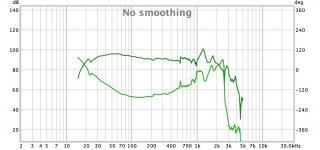
Configuring the sensor low pass filter requires more information. We need to know at what frequency the accelerometer is going to report the first phase/amplitude anomaly. We don't have a frequency plot in the ACI SV12 datasheet, so a near field measurement was taken at the centre of the driver in an existing ported system. From this, it can be seen there is a minor breakup at about 550 Hz and a major one at about 900 Hz. Using the major breakup as a guide, it is suggested the pole for the sensor low pass filter be set to two octaves below this:
Fpxe.high = 225 Hz
Sensor Lowpass Filter:
• Use 68n for C6 (cutoff frequency 234 Hz)
Attachments
Loop Shaping Filter:
This is the tricky part with regard to optimizing the feedback factor and this optimization is left to the user. I won't know the quality of my assumptions and analysis until the circuit is built and tested, but the next posts outline the process I am using to select components for this part of the circuit.
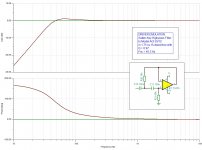
The EVE circuit is modelled in TINA. The following filter models the response of the driver and is added to the output of the Loop Mixer. The Loop Mixer combines the Loop Filter and Adder (summing circuit) functions.
This is the tricky part with regard to optimizing the feedback factor and this optimization is left to the user. I won't know the quality of my assumptions and analysis until the circuit is built and tested, but the next posts outline the process I am using to select components for this part of the circuit.
The EVE circuit is modelled in TINA. The following filter models the response of the driver and is added to the output of the Loop Mixer. The Loop Mixer combines the Loop Filter and Adder (summing circuit) functions.
Attachments
Loop Shaping Filter:
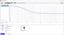
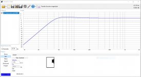
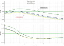
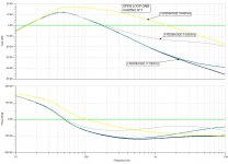
Using the TINA model, AC Analysis was used to generate Open Loop accelerometer feedback responses with varying values of loop filter components C10 and R17 at the output of the PXE GAIN circuitry. These are shown below. Not shown are companion analyses where components selected in the previous steps were varied to see their impact on the open loop response.
From these analyses, these values of the loop filter were "guestimated" as the best compromise for phase and amplitude response to provide good attenuation at higher frequencies and a reasonable phase match to the driver system.
Loop Shaping Filter:
• Use 100n for C10
• Use 10 for R17
Attachments
Last edited:
- Home
- Loudspeakers
- Subwoofers
- MFB for ACI SV12 Drivers using Piratelogic Electronics