I really like MFB.. and a lot of moved air.
Another aspect of this distortion discussion is the opposite... to create harmonics!
Consider those small boxes with a 3" element fooling us with impressive bass response.
What they do is that they add 4th and 6th harmonics from the original low frequency "ompf ompf ompf" and then filter away everything below 300Hz.
You say MFB isn't interesting for PA but consider the following:
1. Current mode amplifiers (so force is proportional to output signal)
2. Ironless or reduced iron motor structures
3. Long throw suspensions and other mechanical parts
If the MFB was good enough a bass driver would not need a flat Bl(x) curve which would mean you could have massive excursion without large motor structures. At the moment you can get drivers that can do 40 mm one way xmax. But they are very expensive mainly because of the massive motor needed. The motor could use much less material.
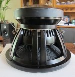
This driver has 90dB sensitivity and a large enough motor to work in a 104L box Q=.707 sealed:
HST-18 mkIII 18″ Subwoofer – Stereo Integrity
In its non xmax limited regime its capable of 123dB/1m with 2000W (assuming no power compression). However its a very expensive driver due to the huge motor.
1. Current mode amplifiers (so force is proportional to output signal)
2. Ironless or reduced iron motor structures
3. Long throw suspensions and other mechanical parts
If the MFB was good enough a bass driver would not need a flat Bl(x) curve which would mean you could have massive excursion without large motor structures. At the moment you can get drivers that can do 40 mm one way xmax. But they are very expensive mainly because of the massive motor needed. The motor could use much less material.
This driver has 90dB sensitivity and a large enough motor to work in a 104L box Q=.707 sealed:
HST-18 mkIII 18″ Subwoofer – Stereo Integrity
In its non xmax limited regime its capable of 123dB/1m with 2000W (assuming no power compression). However its a very expensive driver due to the huge motor.
Kipman725
That is wery intereting.
Iron and huge magnets are heavy and expensive.
Electronics is not (anymore).
Knowing that, you could optimize more towards power handling and excursion.
Letting the BL curve be secondary. Cone breakup is still an important issue but canbe handeled with slightly thicker membrane. And as stated, power is not so much of an issue 2019.
I guess that some "high SPL" woofers for use in CAR Audio will suit perfect for this!
I was sidetracked for a couple of days. But I think we now have some success!
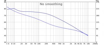
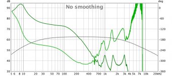
The first image from REW shows the transfer function for the EVE circuit from preamp in to preamp out and the other shows the transfer function for the accelerometer at preamp out when the speaker is fed the signal without going through the EVE circuit.
The speaker was "open baffle" at this point so I couldn't really do the feedback adjustment setup with pink noise recommended in the EVE manual. The response was already pretty flat as measured by a microphone open baffle.
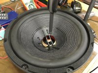
It didn't go perfectly smoothly. I initially had positive feedback and blew a couple of fuses due to oscillation. DEFINITELY USE FUSES. Use smaller values so the oscillation isn't so scary. The feedback seems to be working now by virtue of a significant drop in the system resonance frequency with a corresponding high Q. This is due to the increase in "apparent effective mass". The free-air resonance of the driver is normally around 17 Hz. Note the very small signal level producing large excursions at 8.5 Hz in the video.
Obviously this setup is far from optimal given the driver is not in the enclosure volume the circuit was "optimized" for. The term "optimized" applies loosely at this point.")
There is a bit of 60 Hz hum being picked up by the accelerometer that I need to deal with. I'm not sure where it is coming from at the moment.
The EVE board could do with some test points. In particular, it would be very helpful to have a header in the next version of the EVE servo evaluation board to allow opening and closing the accelerometer feedback loop with a jumper. This would also allow the feedback signal to be easily probed.
The first image from REW shows the transfer function for the EVE circuit from preamp in to preamp out and the other shows the transfer function for the accelerometer at preamp out when the speaker is fed the signal without going through the EVE circuit.
The speaker was "open baffle" at this point so I couldn't really do the feedback adjustment setup with pink noise recommended in the EVE manual. The response was already pretty flat as measured by a microphone open baffle.
It didn't go perfectly smoothly. I initially had positive feedback and blew a couple of fuses due to oscillation. DEFINITELY USE FUSES. Use smaller values so the oscillation isn't so scary. The feedback seems to be working now by virtue of a significant drop in the system resonance frequency with a corresponding high Q. This is due to the increase in "apparent effective mass". The free-air resonance of the driver is normally around 17 Hz. Note the very small signal level producing large excursions at 8.5 Hz in the video.
Obviously this setup is far from optimal given the driver is not in the enclosure volume the circuit was "optimized" for. The term "optimized" applies loosely at this point.
There is a bit of 60 Hz hum being picked up by the accelerometer that I need to deal with. I'm not sure where it is coming from at the moment.
The EVE board could do with some test points. In particular, it would be very helpful to have a header in the next version of the EVE servo evaluation board to allow opening and closing the accelerometer feedback loop with a jumper. This would also allow the feedback signal to be easily probed.
Attachments
Last edited:
Good points which will be included for the next EVE version together with a balanced out to allow easy hookup to UCD amps and an option to add current feedback using this chip.The EVE board could do with some test points. In particular, it would be very helpful to have a header in the next version of the EVE servo evaluation board to allow opening and closing the accelerometer feedback loop with a jumper. This would also allow the feedback signal to be easily probed.
Last edited:
Both current and acceleration feedback?
It is a Christmas present. AKM releases ultra-low noise current sensor AK310x for audio system | News | AKM - Asahi Kasei Microdevices
Copper braid used to de-solder (DAMHIK) can be wrapped as a ground shield...There is a bit of 60 Hz hum being picked up by the accelerometer that I need to deal with.....
B.
Your leads to the accelerometer are placed widely and not twisted for several inches between the installation point and the tinsel lead exit, enough distance to pick up a bit of 60 Hz hum.There is a bit of 60 Hz hum being picked up by the accelerometer that I need to deal with. I'm not sure where it is coming from at the moment.
Minimizing the length of any pick up wire that is not twisted pair ("hum-bucking") between the accelerometer and electronics will reduce hum.
60 Hz is ubiquitous, but nearby mains or power supply transformers can be a particular problem for sensitive transducers, as well as the orientation of the transducer wires to those transformer fields. Moving PSU transformers further away, or changing the angle they sit in relation to the parallel accelerometer leads could reduce hum pick up.
Ben's suggestion to use copper braid wrapped as a ground shield would reduce high frequency (radio frequency/ dimmer hash) noise, but has little effect on low frequency (60 Hz & harmonics) hum noise. Twisted pair cancels common mode noise, allowing phone lines to be run next to AC lines for miles with out hum.
Art
Ben,But I am sure I couldn't successfully solder tiny surface-mount components. Or find replacement bits.
Any suggestions?
Hire someone to do the things you are sure you can't successfully do yourself.
If "time is money", could have saved myself a lot had I taken that advice ;^).
Art
It isn't actually, but if you like noise!
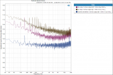
Some measurements with this sensor:
LAX 100-NP | LEM
From top to bottom:
UCD2K ( BTL amp) Lem sensor
UCD180 BTL Lem sensor
UCD single ended current resistor 0,1R with opamp
The AKM has worse noise spec's than the LEM sensor! These Hall sensors are very noisy by nature...
And remember, with MFB the noise floor will be raised with 3-6db above the working range.
Attachments
1. Current mode amplifiers (so force is proportional to output signal)
2. Ironless or reduced iron motor structures
3. Long throw suspensions and other mechanical parts
If the MFB was good enough a bass driver would not need a flat Bl(x) curve which would mean you could have massive excursion without large motor structures. At the moment you can get drivers that can do 40 mm one way xmax. But they are very expensive mainly because of the massive motor needed. The motor could use much less material.
Non linear BL / Xmax behaviour indeed is one of the main causes of distortion and servo drive can help addressing the issue but only sofar as thermal management allows. The same applies to current drive, compensating for BL or power compression by increasing the current through the VC causes extra voicecoil heating which in my opinion makes the technology less favourable for use with high power systems. Which might explain why proaudio still is very much voltage driven.
This driver has 90dB sensitivity and a large enough motor to work in a 104L box Q=.707 sealed:
HST-18 mkIII 18″ Subwoofer – Stereo Integrity
In its non xmax limited regime its capable of 123dB/1m with 2000W (assuming no power compression). However its a very expensive driver due to the huge motor.
I've done a CSS SDX12 which looks promising too ...
I'm not convinced current drive is something worthwhile pursuing due to above mentioned thermal issues but am curious about its effect on distortion. I have not tried it yet because the tpa3116 amplifiers I'm using don't lend themselves to easy implementation due to their BTL design requiring a floating sense R while most implementations being single ended designs. The AKM employs a hall sensor offering a fully insulated sense R allowing it to be used with btl setups. It's usability in combination with MFB remains to be seen for reasons highlighted by ds23man but for use with midbass / mid channels - where adding accelerometers is critical from a mms perspective - the approach might do the trick.So is the new AKM sensor THE device to use in future MFB-projects..?
Attachments
Last edited:
Thanks Ben and Art for your input on the 60 Hz hum problem I mentioned in my previous post! Electronics is not my forte.
Not a heck of a lot I can do about that..
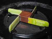
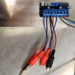
I used the same shielded cable I was using for the old MFB system with the Philips driver. This cable starts right at the accelerometer terminals at the speaker. I do however have a second short run of untwisted wires for a flying female phono connector for convenience during testing - see picture. I did find that making a connection to mains power ground at the EVE power ground reduced hum a lot, but it didn't eliminate it.
The shielded cable is quite long (several meters) and I thought this might be an issue, but I replaced it with a very short one and it made no noticeable difference in the level of hum.
Your leads to the accelerometer are placed widely and not twisted for several inches between the installation point and the tinsel lead exit, enough distance to pick up a bit of 60 Hz hum.
Not a heck of a lot I can do about that.
. Minimizing the length of any pick up wire that is not twisted pair ("hum-bucking") between the accelerometer and electronics will reduce hum.
I used the same shielded cable I was using for the old MFB system with the Philips driver. This cable starts right at the accelerometer terminals at the speaker. I do however have a second short run of untwisted wires for a flying female phono connector for convenience during testing - see picture. I did find that making a connection to mains power ground at the EVE power ground reduced hum a lot, but it didn't eliminate it.
The shielded cable is quite long (several meters) and I thought this might be an issue, but I replaced it with a very short one and it made no noticeable difference in the level of hum.
Attachments
There is a bit of 60 Hz hum being picked up by the accelerometer that I need to deal with. I'm not sure where it is coming from at the moment.
Make sure to ground the driver chassis, the StarBass connection board does so by connecting the - pole via the mounting screw. If that still gives no joy and the tinsel wires are the suspect you might want to try some mogami cable.
The Pirate MFB device looks very nice to me and I could use one now. But I am sure I couldn't successfully solder tiny surface-mount components. Or find replacement bits.
Any suggestions?
B.
I was also unsure about doing surface mount. In no particular order, here are some suggestions/recommendations based on my recent experience:
1. You can order the boards from Chris to populate all common components so all that is left are a few SMDs and some through-hole (extra cost).
2. You could complete a design with simulation to determine values for components like R17 and C10 in advance and provide the info to Chris and he might be able to populate the whole thing for you (extra cost).
3. Get a pair of prescription glasses for close up work. For me this was HUGE. These are not reading glasses - their optimum focal range is less than half the distance for reading glasses but I can see EVERYTHING.
4. View YouTube videos on how to do SMD.
5. Use solder paste and hot air. This requires less manual dexterity and precision.
6. Get the needed tools if you don't already have them. An inexpensive hot air rework station, good solder paste, PWB holder/clamp/vice, proper fine tweezers, extra fine tip for your current soldering iron, etc.
7. Light. Lots of it.
Make sure to ground the driver chassis, the StarBass connection board does so by connecting the - pole via the mounting screw. If that still gives no joy and the tinsel wires are the suspect you might want to try some mogami cable.
Aha! Thanks, Chris!
I didn't notice the grounding connection on the accelerometer connection board. I have it isolated with insulating washers at the moment so I'll correct that. This will have to wait as I am working on the enclosure now. More to follow...
Many thanks for all the good suggestions....Get a pair of prescription glasses for close up work. For me this was HUGE. These are not reading glasses - their optimum focal range is less than half the distance for reading glasses but I can see EVERYTHING.
You can buy flip-on magnifiers to clip to eyeglasses. And a "miner's lamp" on a headband. And... it take all day to list my seeing tools.
BTW, Zenni (web eyeglasses) makes a lens that is sort of both a bifocal and progressive; it has up-close on the bottom half and middle-range (like for computer screens and up to a dozen feet or so) on the upper half. Unique and great concept. I think of mine as "at home... indoors" use.
OK we got seeing nailed down. Now how about something that helps my hands move by the millimetre? Or those tasks that need three or four hands?
(No intention to highjack this great thread with any more old-guy posts but surface mount soldering is an obstacle for many, no doubt. Can't see why PirateLogic had to make the pre-amp so (nice and) small and not go further in offering wired-up kits.)
B.
Last edited:
- Home
- Loudspeakers
- Subwoofers
- MFB for ACI SV12 Drivers using Piratelogic Electronics