No, but i think it is an example of why a taped qw pipe folded like a ROAR works as it does or can be optimized for a set of TS parameters.
If circlomennen wanted to entertain the idea i think he might agree. but a mass loaded ROAR/paraflex, is the most interesting 6/8th order box in the world. Regardless if its one or the other name. the ‘name’ is just a distance or CSA shuffle from another phase altercation. .but since that is a big change, there are names to them that fase with length or area at or after the rear output tap.
If circlomennen wanted to entertain the idea i think he might agree. but a mass loaded ROAR/paraflex, is the most interesting 6/8th order box in the world. Regardless if its one or the other name. the ‘name’ is just a distance or CSA shuffle from another phase altercation. .but since that is a big change, there are names to them that fase with length or area at or after the rear output tap.
If you explore different 6th and 8th order designs along a spectrum from lame to wild ideas you will stumble across a few nodes where different aspects will create great synergistic effects that will lift that design to a whole other level compared to the rest.
I believe ROAR and HROAR as just such synergistic "nodes" of simplicity (considering it being a high order BP design) and performance.
I can add lots of complexity and parts, and maybe gain a few percent performance in one way or another, but I strive for simplicity and usability. The HROAR is very easy and simple to build with very few parts that make up the high order QW bandpass design.
The HROAR has a very usable form and size for its performance. It is easy to place close to a wall where it will occupy very little space from a living room, studio, hometheater, or movie theater, bar, nightclub or restaurant.
There are no 180 degree bends in the QW path. Only 90 degree bends. This might not make a lot of difference at low levels, but once you start pushing kilowatts into it it will matter greatly.
The tapped non expanding pipe has a very generous cross section area and the mouth is 120-150% of the driver SD for very low air particle velocities at very high power levels.
The driver is turned 90 degrees sideways to the port exit to avoid losses due to the large moving mass of the cone, voice coil and suspension of typical car bass drivers.
Remember that a 1000 to 1 mass difference between the box and the moving mass of the driver constitutes a 40 dB mechanical signal to noise level. You would not accept 40 dB signal to noise from the electronics. Turning the driver sideways to the radiating direction of the mouth does make a huge difference in punch and attack and the dynamic reproduction of music. (See PPSL for more discussions and examples of this).
Some random thoughts and ideas behind the ROAR and HROAR design.
After making many complex higher order qw enclosures. It became increasingly difficult to pinpoint the exact reason why they all (while very different in detsals had a certain undeniable crack of a window to a slight sensation known as ‘punch’ by many folks.
after getting deep into many designs it became way too rabbit hole and i had half a dozen boxes stacked up in as many months and was nearly laying out Front loaded/ rear vented compound horns when it was obvious it had strayed into way too deep.
back up and a couple plain jane Qw TLs later. I decided paraflex was two closed pipes short and wide at 80 cm and long and skinny at 240cm.
That and a CSA split was a monster, but it was only the beginning. Because theres another pA’raflex. its chamber is offset. and lengthwise, not width. but at 90 degrees from the entry point( ????) what is it?
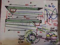
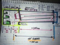
Its a sideways roar. The roar is the same but swapped that chamber to long and skinny inline, not offset and perpendicular. I didnt really notice driver position as much as chamber orientation. But i ended up with the top drawing and with a lot of help and questions that got me sent all over examples of higher order qw stuff like bose, olson, etc. i think i might see a trend??
Possible point being poorly drawn but its showing the two 5Fb and one 3Fb harmonic as Pressure wave nulls getting
Bonked by the lengths used here in CM? 80 /240 amd 120/240 and the interval of the offset position seems to be at (or technically just off) the point of removing those first two pressure ‘dumps’ by the lengths used in folds or to start/exit, or driver location.
Having used the same driver and multiple higher qw layouts with the same tuning objective and subsequently nearly the sane general CSA and legths span of distribution in at least 3 dozen simmed and 3 wooden. i think its time i get a second opinion, instead of ignorantly poking around guessing ??
??
What(if anything ) do you see/hear/or notice in any of the roar or Hroar layouts or segmental lengths used? Is there higher order harmonics playing cooperatively, by chance? Or am i smoking the wrong stuff(again)
after getting deep into many designs it became way too rabbit hole and i had half a dozen boxes stacked up in as many months and was nearly laying out Front loaded/ rear vented compound horns when it was obvious it had strayed into way too deep.
back up and a couple plain jane Qw TLs later. I decided paraflex was two closed pipes short and wide at 80 cm and long and skinny at 240cm.
That and a CSA split was a monster, but it was only the beginning. Because theres another pA’raflex. its chamber is offset. and lengthwise, not width. but at 90 degrees from the entry point( ????) what is it?
Its a sideways roar. The roar is the same but swapped that chamber to long and skinny inline, not offset and perpendicular. I didnt really notice driver position as much as chamber orientation. But i ended up with the top drawing and with a lot of help and questions that got me sent all over examples of higher order qw stuff like bose, olson, etc. i think i might see a trend??
Possible point being poorly drawn but its showing the two 5Fb and one 3Fb harmonic as Pressure wave nulls getting
Bonked by the lengths used here in CM? 80 /240 amd 120/240 and the interval of the offset position seems to be at (or technically just off) the point of removing those first two pressure ‘dumps’ by the lengths used in folds or to start/exit, or driver location.
Having used the same driver and multiple higher qw layouts with the same tuning objective and subsequently nearly the sane general CSA and legths span of distribution in at least 3 dozen simmed and 3 wooden. i think its time i get a second opinion, instead of ignorantly poking around guessing
?? What(if anything ) do you see/hear/or notice in any of the roar or Hroar layouts or segmental lengths used? Is there higher order harmonics playing cooperatively, by chance? Or am i smoking the wrong stuff(again)
Attachments
It seems (to me), this design takes a standard Qw for a medium/small Vas, and can be made appropriate for Qts (.4 @Fs, <0.4 above Fs farther and farther, <0.4 below (careful of the size and mass of lots of to be pushed air though!) and then squirts it through another air pump(tapped motor side output) and the expanded area has a window (vent) for the bottleneck and burst release. this has audible significance and even if not mass loaded at exit. either way(wide mouth ROAR)or aperture(Hroar), its boosting and punching out a signal that can/could/is depending on how its needed( ?) already ‘ideal’ for the second effect ‘boosting it acousticslly?
If boost garbage you get loud garbage. If you boost a signal thats 90 out at fundamental and hits 180(opposites) at 100hz or so just as stated, whats not to love?
it can have GD or not. it can have anything. But it certainly can be FANTASTiC and i think ive come closer and closer to that impossible ‘perfect’ .
But a ROAR as pictured (above) is (it seems) to be the best ‘uncompmicatedway for my TS parameters and any high order pipe i sim or have built and simmed or have yet to??
I believe ROAR and HROAR as just such synergistic "nodes" of simplicity (considering it being a high order BP design) and performance.
Johannes, for pa system do you prefer ROAR or HROAR? I have RCF 18p400 and will build bass cab for 40hz - 120hz. Thank you in advanc.
For PA and mostly outdoor use I would prefer the normal ROAR18 design. It will do 40 - 120 Hz.
I do not know if your driver is suitable for the ROAR18 design. I will test it in Hornresp later today, once my main workstation is up and running.
The HROAR design is better suited for car audio drivers with very large Mms and very low Vas, even though there are some PRO drivers that seems to work well in this design to.
The HROAR is better for small to medium indoor venues, like small clubs, restaurants etc, where the shallow depth makes it easy to push it up to a wall or under a podium and save a lot of space. The normal ROAR is a lot deeper and does need some space to "breathe" for optimum performance.
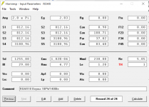
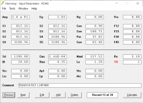
ROAR18 Hornresp RCF L18P400
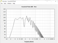
I have simulated on hornresp. The result is no noticeable difference against the recommended driver Beyma 18PW1400fe. See attached file, Black = L18P400, Gray = 18PW1400fe.
Maybe I'll make one in the next few months
I have simulated on hornresp. The result is no noticeable difference against the recommended driver Beyma 18PW1400fe. See attached file, Black = L18P400, Gray = 18PW1400fe.
Maybe I'll make one in the next few months
Attachments
For PA and mostly outdoor use I would prefer the normal ROAR18 design. It will do 40 - 120 Hz.
I do not know if your driver is suitable for the ROAR18 design. I will test it in Hornresp later today, once my main workstation is up and running.
The HROAR design is better suited for car audio drivers with very large Mms and very low Vas, even though there are some PRO drivers that seems to work well in this design to.
The HROAR is better for small to medium indoor venues, like small clubs, restaurants etc, where the shallow depth makes it easy to push it up to a wall or under a podium and save a lot of space. The normal ROAR is a lot deeper and does need some space to "breathe" for optimum performance.
I dont know if i can blur that for us all, or if im just confusing. But its all in the name of high order qw pipes and how to approach them for a variety of needs? This is a 10” dayton audio rss265ho4 btw.
I decided to start with a simple 4th order ‘Offset driver TL’ this time and then get some baseline data to compare to the ‘bolt on’ flanges extras. previously ive been stuck trying to refer to a sim to explain ‘poorly’ what i was aiming at (and never knew what to reference or to help explain anything??) i hope this helps, instead of just contributing ‘confusion’, and not being helpful to paraflex, Roar, Hroar, altcon paraflex, big mouth tapped pipes and halfwave chambered phase gapping craziness...
Any ‘pointers’ or advice is 100% appreciated.
this is a ‘mess’ but i wanted to show the offset position initially, because its significant in its length and of subsequent applications further on down the ‘pipe’ as we add higher orders(imho)?? ‘simple’ is best. But first i gotta find the chaos to avoid masterAttachments
Last edited:
For PA and mostly outdoor use I would prefer the normal ROAR18 design. It will do 40 - 120 Hz.
I do not know if your driver is suitable for the ROAR18 design. I will test it in Hornresp later today, once my main workstation is up and running.
The HROAR design is better suited for car audio drivers with very large Mms and very low Vas, even though there are some PRO drivers that seems to work well in this design to.
The HROAR is better for small to medium indoor venues, like small clubs, restaurants etc, where the shallow depth makes it easy to push it up to a wall or under a podium and save a lot of space. The normal ROAR is a lot deeper and does need some space to "breathe" for optimum performance.
I dont know if i can blur that for us all, or if im just confusing. But its all in the name of high order qw pipes and how to approach them for a variety of needs?
I decided to start with a simple 4th order ‘Offset driver TL’ this time and then get some baseline data to compare to the ‘bolt on’ flanges extras. previously ive been stuck trying to refer to a sim to explain ‘poorly’ what i was aiming at (and never knew what to reference or to help explain anything??) i hope this helps, instead of just contributing ‘confusion’, and not being helpful to paraflex, Roar, Hroar, altcon paraflex, big mouth tapped pipes and halfwave chambered phase gapping craziness...
Any ‘pointers’ or advice is 100% appreciated.

This wicked monster found its way into our living room again.
I did some measurements and some EQ plus crossover work to get it to behave reasonably well in our living room. I just want to share what can be achieved with a small amount of EQ and a 48 dB/octave crossover at 90 Hz.


Raw versus EQ plus Xover in both graphs.
Quite respectable objective performance coming from a dB-monster developed for car audio spl competition.
There is a long L34 section before the Helmholtz chamber to add a lot of acoustic positive feedback - which explains the ragged raw response. The driver will get an substantial virtual Bl-boost over part of the pass band.But the ragged raw response is just a indicator of a very strong motor system with a lot of power to drive the resonators in a quite heavy handed way. This translates into a very physical, tactile and vivid bass reproduction. It is felt throughout the load bearing structure in our house more then actually heard in our living room. It is totally useless for late night listening or HT use, but very fun once I am alone in our house. I watched the sci-fi movie Passenger yesterday and it adds an "live" realism to the sound track that is very addictive and enjoyable.
Last edited:
View attachment 964307
This wicked monster found its way into our living room again.
I did some measurements and some EQ plus crossover work to get it to behave reasonably well in our living room. I just want to share what can be achieved with a small amount of EQ and a 48 dB/octave crossover at 90 Hz.
View attachment 964308
View attachment 964309
Raw versus EQ plus Xover in both graphs.
Quite respectable objective performance coming from a dB-monster developed for car audio spl competition.
There is a long L34 section before the Helmholtz chamber to add a lot of acoustic positive feedback - which explains the ragged raw response. The driver will get an substantial virtual Bl-boost over part of the pass band.But the ragged raw response is just a indicator of a very strong motor system with a lot of power to drive the resonators in a quite heavy handed way. This translates into a very physical, tactile and vivid bass reproduction. It is felt throughout the load bearing structure in our house more then actually heard in our living room. It is totally useless for late night listening or HT use, but very fun once I am alone in our house. I watched the sci-fi movie Passenger yesterday and it adds an "live" realism to the sound track that is very addictive and enjoyable.
it's possible to have the plans?
Post 53 in this thread contains the only "plans" that was ever made of this design. It is a one off build for a specific car. I believe there is a Hornresp data picture somewhere below post 53.
But the driver is out of stock and was previously only available in Sweden. It was a rather odd driver with lots of Bl and quite low Qts.
But the driver is out of stock and was previously only available in Sweden. It was a rather odd driver with lots of Bl and quite low Qts.
Last edited:
HROAR SLOW - YouTube
A short video of the port mouth amplitude at somewhere below 70 watts.
My HROAR is powered from a single channel from my JBL STAGE A6002.
The signal is a single 32 Hz CEA-2010 burst filmed at 960 fps. It is easy to use 0.25 x playback speed in the youtube video player.
I have no idea if this is interesting in any way to anyone, but I am bored and wanted to see the mouth behavior in slowmotion myself, so I can just as well post it here while I am at it.
Mynningsbeteende ROAR12 - YouTube
A similar video of my original ROAR12. A friend made this video. He was playing bass guitar through it with a 20 watt amp, and he covered the mouth with a towel.
A similar video of my original ROAR12. A friend made this video. He was playing bass guitar through it with a 20 watt amp, and he covered the mouth with a towel.

- Home
- Loudspeakers
- Subwoofers
- ROAR with Helmholtz front resonator