my experience with micro array is the dip in upper case mid section. which results in compensating and lots of distortiob. you can use the empty space behind the CD to extend horn path.
 I don't understand what you mean. Please clarifiy.
Thanks
sorry, typing from mobile. micro arrays have little to no upper bass and midbass. or in other words can not push enough air to let it kick. so you want to push them harder which leads to more distortion.
I'd use them with bass bins, anyway. What I love about full rangers is the fact that you don't have to Xo them in the critical range. Plus, they are small and unobtrusive, which is really nice in, lets say, old churches and such.
Information about small drivers versus large , technical challenges, etc ..
Using small drivers for this range and in this sort of design is typically not the most cost effective solution because you have to employ so many more of the small drivers to generate enough midbass efficiency, and SPL and therefore the highly demanding dynamic headroom & midbass presence required for PA work........ In the end when you compare money spent versus max SPL capability the larger diameter drivers are generally a better value... Unless you can find a source for inexpensive 6" or 8" PA drivers with the right parameters and use a heck of a lot of them....... .............
The Peerless/Tymphany TC9 model that GKH mentioned is not appropriate because it's SPL rating is far too low to be used in any sort of PA application......It would burn up before delivering the levels of midrange output that are needed .....................
As far as small drivers are concerned a better choice might be some of the Faital Pro drivers (or similar), they offer smaller diameter drivers with high SPL ratings..... The sort of drivers that you could make a nice "column" style speaker out of, but in that case (regardless of the upper bandwidth capabilities of a single driver) your crossover point is limited by the center-to-center spacing between the drivers in the array otherwise the vertical off-axis response can get excessively messy above a certain frequency (destructive interference which isn't consistent enough resulting in severely jagged response due to the rough comb filtering off-axis vertically*) ....
....
Our approach is different here though .....
It is important to note that the upper midrange projection from these larger diameter drivers (like 10" , 12" and 15") is "beamy" in nature which means there is a lack of dispersion....... We are talking about the 1khz to 3khz range , right up to where the HF array takes over...... This "beamy" quality is normally seen as an undesirable limitation but we are actually using it to our advantage here in terms of the vertical axis, and this also comes into play when making vertical arrays out of these modules, (and relates to the interaction that i mentioned in the previous paragraph*) ...... Speaker design is all about choosing your compromises wisely and in this case we are basically accepting some amount of inevitable "lobing" when arraying with these beamy drivers as a workaround to avoid some other issues that would normally plague a system with center-to-center driver spacings that are further apart than what is considered ideal ..........It is all such tricky business and Physics is a harsh Mistress ............. To be fair this is not an absolutely perfect solution but it is affordable and practical and it will get the job done
  ........
Technically speaking line-array systems rarely are perfect, there is always a compromise of some sort (otherwise they cost a fortune and then the price is it's compromise! ).....
In regards to the horizontal plane it is a much simpler matter.. Our toed-in crossfiring style baffle helps us to maintain some amount of useful horizontal dispersion through the upper midrange... ........
Using small drivers for this range and in this sort of design is typically not the most cost effective solution because you have to employ so many more of the small drivers to generate enough midbass efficiency, and SPL and therefore the highly demanding dynamic headroom & midbass presence required for PA work........ In the end when you compare money spent versus max SPL capability the larger diameter drivers are generally a better value... Unless you can find a source for inexpensive 6" or 8" PA drivers with the right parameters and use a heck of a lot of them.......
.............The Peerless/Tymphany TC9 model that GKH mentioned is not appropriate because it's SPL rating is far too low to be used in any sort of PA application......It would burn up before delivering the levels of midrange output that are needed
.....................As far as small drivers are concerned a better choice might be some of the Faital Pro drivers (or similar), they offer smaller diameter drivers with high SPL ratings..... The sort of drivers that you could make a nice "column" style speaker out of, but in that case (regardless of the upper bandwidth capabilities of a single driver) your crossover point is limited by the center-to-center spacing between the drivers in the array otherwise the vertical off-axis response can get excessively messy above a certain frequency (destructive interference which isn't consistent enough resulting in severely jagged response due to the rough comb filtering off-axis vertically*)
.... Our approach is different here though .....
It is important to note that the upper midrange projection from these larger diameter drivers (like 10" , 12" and 15") is "beamy" in nature which means there is a lack of dispersion....... We are talking about the 1khz to 3khz range , right up to where the HF array takes over...... This "beamy" quality is normally seen as an undesirable limitation but we are actually using it to our advantage here in terms of the vertical axis, and this also comes into play when making vertical arrays out of these modules, (and relates to the interaction that i mentioned in the previous paragraph*) ...... Speaker design is all about choosing your compromises wisely and in this case we are basically accepting some amount of inevitable "lobing" when arraying with these beamy drivers as a workaround to avoid some other issues that would normally plague a system with center-to-center driver spacings that are further apart than what is considered ideal ..........It is all such tricky business and Physics is a harsh Mistress
............. To be fair this is not an absolutely perfect solution but it is affordable and practical and it will get the job done ........Technically speaking line-array systems rarely are perfect, there is always a compromise of some sort (otherwise they cost a fortune and then the price is it's compromise!
).....In regards to the horizontal plane it is a much simpler matter.. Our toed-in crossfiring style baffle helps us to maintain some amount of useful horizontal dispersion through the upper midrange...
........It can be done =)
USRFobiwan,
Yes , this is a very good point ... You certainly can open up the chamber around the compression driver , and you can do it with a taper , this is how Mr Vansickle built his .... He was able to fit some Dayton DT250P compression drivers which have a motor diameter of 4.7" ...... It will alter the LF path profile a bit , you just have to account for it in the sim to make sure that the performance is still acceptable (and in this case it was) ..
Another option is to put the HF waveguide out in front of the midbass/midrange drivers , this makes the design MUCH easier .......
You could even use a standard horn and compression driver combination mounted out front in the same way if you don't plan on arraying multiples of these cabinets vertically ...
If you appreciate BFM's melded or straight piezo arrays made out of Goldwood 1016s then you could even go that route if you really wanted .......... There are ways to make the piezos sound more acceptable, damping and specialized networks and such, it does take some effort but it can be done if you have the time to work through it...This idea is especially feasible if you buy plenty of extra piezos (many of which you might discard or load with GRS elements in order to come up with an array set that measures well) , i went into some detail about it over in my old Transflex/Karlflex discussion ..... The piezo tinkering is fun but it is probably best reserved for those who are gluttons for punishment and have extra time on their hands to refine it and get it right .....
may I suggest to make more room around the CD driver. not all CD drivers have 100mm perfect cross diameter. this limit the design. also what about a few degree from front to back, between 4 an 6 deg. tapper.
USRFobiwan,
Yes , this is a very good point ... You certainly can open up the chamber around the compression driver , and you can do it with a taper , this is how Mr Vansickle built his .... He was able to fit some Dayton DT250P compression drivers which have a motor diameter of 4.7" ...... It will alter the LF path profile a bit , you just have to account for it in the sim to make sure that the performance is still acceptable (and in this case it was) ..
Another option is to put the HF waveguide out in front of the midbass/midrange drivers , this makes the design MUCH easier .......
You could even use a standard horn and compression driver combination mounted out front in the same way if you don't plan on arraying multiples of these cabinets vertically ...
If you appreciate BFM's melded or straight piezo arrays made out of Goldwood 1016s then you could even go that route if you really wanted .......... There are ways to make the piezos sound more acceptable, damping and specialized networks and such, it does take some effort but it can be done if you have the time to work through it...This idea is especially feasible if you buy plenty of extra piezos (many of which you might discard or load with GRS elements in order to come up with an array set that measures well) , i went into some detail about it over in my old Transflex/Karlflex discussion ..... The piezo tinkering is fun but it is probably best reserved for those who are gluttons for punishment and have extra time on their hands to refine it and get it right .....
Last edited:
ad "Micro Array"
I apologize for not having made it clear enough that I never intended to use such a system for, say, heavy metal PA work. That these tiny full range speakers would never reach extremely high SPL is obvious. But, as user Wesayso et al have shown in their line array threads, with proper EQ, reasonable SPL can be reached without distortion. Besides, I'd never dare to drive such a system lower than 180Hz.
ad "Full Size" array:
If I move the HF waveguide forward, doesn't it play havoc with low/mid directivity?
Last edited:
I see gkh, for non extreme pa use it makes sense. but then it makes more sense to just place some full ranges. ...
Thank you
Well, if it were possible to use MMJ's design for a box with 2x8 TC9s, I'd love to invest and build a prototype.
...
I wonder how 12" design will Sim with let's say two eminence Delta pro 12a.
Me too
Regds
Gerald
Yes , the Delta Pro12A is a good option
Hey guys ,
The Delta Pro12A is a great choice for these Super Planar Line-Array modules and wideband kickbins with the Toed-In Crossfiring style baffles ..... Notice that it has the desirable rising upper-mid response......Take a look at the chart that Eminence published for that driver to see what i am talking about (NOTE: the curve is similar to what we see with the Delta-10A) ........
https://www.parts-express.com/pedocs/specs/290-510--eminence-delta-pro-12a-specifications.pdf
The Kappalite 3012HO is a step up with it's higher Xmax rating, slightly more motor force, and an even more pronounced rising upper-mid response ... The lighter weight is nice too ....
https://www.parts-express.com/pedocs/specs/290-589--eminence-kappalite-3012ho-specifications.pdf
We tried the Eminence LA12850 drivers in a set of these Super Planars, and they are great with their high motor force figure, shallow mounting depth, and extreme power handling but their upper-mid response is not as good without enough "rise" and with it's peak landing in the wrong spot right around 1.25khz ..... That upper-mid peak would ideally be higher up around 2khz or 2.5khz unless we were to design the HF waveguide to come in at around 1.5khz (and in that case it would be fine, but would require compression drivers that are more expensive and robust, and might not fit in the available chamber) .............. Don't get me wrong , these boxes did sound good but after hearing the recordings of them i could tell that the vital vocal clarity sounded slightly recessed in the mix to me (needed a little more in the 1.5khz to 2khz range) but that could just be the perfectionist in me speaking .... Unfortunately i was not able to hear these in person because they were built in North Carolina and I am in Arizona ..
https://www.parts-express.com/pedocs/specs/290-547--eminence-la12850-specifications.pdf
Hey guys ,
The Delta Pro12A is a great choice for these Super Planar Line-Array modules and wideband kickbins with the Toed-In Crossfiring style baffles ..... Notice that it has the desirable rising upper-mid response
......Take a look at the chart that Eminence published for that driver to see what i am talking about (NOTE: the curve is similar to what we see with the Delta-10A) ........https://www.parts-express.com/pedocs/specs/290-510--eminence-delta-pro-12a-specifications.pdf
The Kappalite 3012HO is a step up with it's higher Xmax rating, slightly more motor force, and an even more pronounced rising upper-mid response ... The lighter weight is nice too
.... https://www.parts-express.com/pedocs/specs/290-589--eminence-kappalite-3012ho-specifications.pdf
We tried the Eminence LA12850 drivers in a set of these Super Planars, and they are great with their high motor force figure, shallow mounting depth, and extreme power handling but their upper-mid response is not as good without enough "rise" and with it's peak landing in the wrong spot right around 1.25khz ..... That upper-mid peak would ideally be higher up around 2khz or 2.5khz unless we were to design the HF waveguide to come in at around 1.5khz (and in that case it would be fine, but would require compression drivers that are more expensive and robust, and might not fit in the available chamber) .............. Don't get me wrong , these boxes did sound good but after hearing the recordings of them i could tell that the vital vocal clarity sounded slightly recessed in the mix to me (needed a little more in the 1.5khz to 2khz range) but that could just be the perfectionist in me speaking
.... Unfortunately i was not able to hear these in person because they were built in North Carolina and I am in Arizona .. https://www.parts-express.com/pedocs/specs/290-547--eminence-la12850-specifications.pdf
I wanted the 3010HO to be good as well =/ but for some reason
Gkh,
I had checked into the 3010HO hoping for the same sort of curve as what we see on the 3012HO , and unfortunately it looks like something didn't translate well in the 10" version , something material or geometry related i guess but they weren't able to nail that same curve ..
..
http://www.eminence.com/pdf/Kappalite_3010HO.pdf
The Delta-10A looks pretty good though ..
http://www.eminence.com/pdf/Delta_10A.pdf
Gkh , I am preparing some more information for you right now .... Will post in a moment ..
Hey MMJ,
so in my case would the Kappalite 3010HO be the speaker of choice?
Gkh,
I had checked into the 3010HO hoping for the same sort of curve as what we see on the 3012HO , and unfortunately it looks like something didn't translate well in the 10" version , something material or geometry related i guess but they weren't able to nail that same curve
.. http://www.eminence.com/pdf/Kappalite_3010HO.pdf
The Delta-10A looks pretty good though ..
http://www.eminence.com/pdf/Delta_10A.pdf
Gkh , I am preparing some more information for you right now .... Will post in a moment ..
That is a great question, and i am sure many other have wondered the same, as i have
Gkh,
That is an excellent question..... Oddly enough and as counterintuitive as it may seem the HF array being placed out in front of the LF/MF drivers doesn't really seem to cause any problems regarding low/mid directivity.... This is within reason of course, i mean surely we cannot block too much of the mouth's CSA , so as long as we don't go overboard we are fine here .....
.....
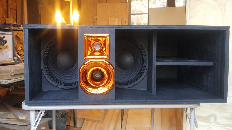
Take a look at the Super Planar Club Tops (wideband kickbin horn) , the photo is below , it is the set with the golden looking horns ....... Surprisingly that cabinet produced a measured response curve that was more smooth than the Symmetrical Path style Super planar Line-Array cabinets when compared .... The reason the Super Planar Club Tops measured relatively well probably had to do with the fact that the front chamber was deeper and the two 12" drivers were "spanned" at different offsets while sharing the same path ...... The midrange and HF horns being placed out in front of the 12" drivers turned out to be a great strategy in this case
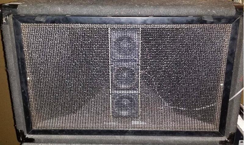
My Electrovoice SH-1810 midrange horns also use an arrangement with the HF array placed well out in front of the 10" midrange driver ..... They were originally arranged this way from the factory, and i just replaced their compression driver with a special piezo array and network ..... The crossover point is 2khz on these with very sharp curves (minimal overlap, which is important here) ..
 .
.
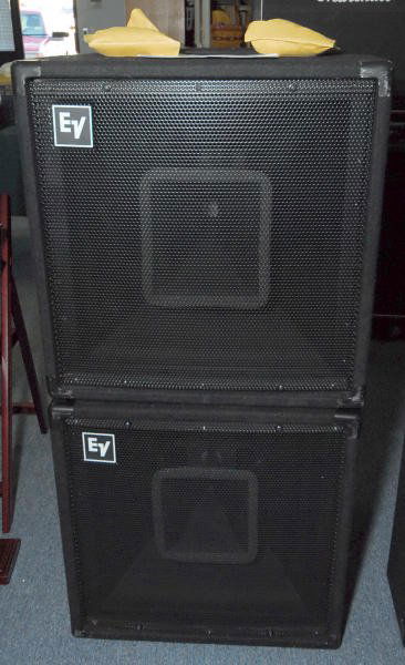
Here is another example of an Electrovoice (EV) brand midrange horn with the HF compression driver and it's horn placed out in front of what is probably a 10" or 12" LF/MF driver in this cabinet...
This is just a convenient and practical way to do it, and performance can be great
Some of the cabinets designed by Bill Fitzmaurice also use this same sort of configuration .... Here is a photo of his Omnitop series cabinet ... This is one of the more popular BFM designs over the years .....

This strategy may also have an additional benefit ...... I will explain ...
When i was doing the work to refine my Xfmr driven piezo arrays i performed a lot of experiments and I took a lot of measurements ...... One of these experiments was an attempt to figure out how placing the HF array recessed further into the cabinet would alter it's performance, and what i found out was that the array's response was degraded when placed further into the cabinet ...... The array did not like being recessed ..... It preferred being placed at the very front of the cabinet but separated from the front grill by about 1/2 inch ....
I cannot say for certain that all HF arrays will behave this same way when recessed but this was just my experience with the Piezo array ........ It is possible that the vertical dispersion pattern on the Line-Array style HF waveguide is tighter so perhaps it is less subject to degradation when recessed ...... We won't know for sure until someone performs the experiment with measurements to verify at different recess depths ..
ad "Full Size" array:
If I move the HF waveguide forward, doesn't it play havoc with low/mid directivity?
Gkh,
That is an excellent question..... Oddly enough and as counterintuitive as it may seem the HF array being placed out in front of the LF/MF drivers doesn't really seem to cause any problems regarding low/mid directivity.... This is within reason of course, i mean surely we cannot block too much of the mouth's CSA , so as long as we don't go overboard we are fine here
..... Take a look at the Super Planar Club Tops (wideband kickbin horn) , the photo is below , it is the set with the golden looking horns ....... Surprisingly that cabinet produced a measured response curve that was more smooth than the Symmetrical Path style Super planar Line-Array cabinets when compared .... The reason the Super Planar Club Tops measured relatively well probably had to do with the fact that the front chamber was deeper and the two 12" drivers were "spanned" at different offsets while sharing the same path ...... The midrange and HF horns being placed out in front of the 12" drivers turned out to be a great strategy in this case
My Electrovoice SH-1810 midrange horns also use an arrangement with the HF array placed well out in front of the 10" midrange driver ..... They were originally arranged this way from the factory, and i just replaced their compression driver with a special piezo array and network ..... The crossover point is 2khz on these with very sharp curves (minimal overlap, which is important here) ..
Here is another example of an Electrovoice (EV) brand midrange horn with the HF compression driver and it's horn placed out in front of what is probably a 10" or 12" LF/MF driver in this cabinet...
This is just a convenient and practical way to do it, and performance can be great
Some of the cabinets designed by Bill Fitzmaurice also use this same sort of configuration .... Here is a photo of his Omnitop series cabinet ... This is one of the more popular BFM designs over the years .....
This strategy may also have an additional benefit ...... I will explain ...
When i was doing the work to refine my Xfmr driven piezo arrays i performed a lot of experiments and I took a lot of measurements ...... One of these experiments was an attempt to figure out how placing the HF array recessed further into the cabinet would alter it's performance, and what i found out was that the array's response was degraded when placed further into the cabinet ...... The array did not like being recessed ..... It preferred being placed at the very front of the cabinet but separated from the front grill by about 1/2 inch ....
I cannot say for certain that all HF arrays will behave this same way when recessed but this was just my experience with the Piezo array ........ It is possible that the vertical dispersion pattern on the Line-Array style HF waveguide is tighter so perhaps it is less subject to degradation when recessed ...... We won't know for sure until someone performs the experiment with measurements to verify at different recess depths ..
Last edited:
This adds up to what I thought: The two (golden) horns leave a lot of open space, so they wouldn't disturb directivity too much. Mr. V's waveguide, on the other hand, is something like a block, therefore my suspicion.
The Frankenpiezos are something I had in mind, too - but I shy away from dis- and reassembling a lot of them...
One thing thgat might be interesting is building an array of rectangular piezos like this: https://www.mcmelectronics.com/product/MONACOR-MPT-025-/53-5040
The Frankenpiezos are something I had in mind, too - but I shy away from dis- and reassembling a lot of them...
One thing thgat might be interesting is building an array of rectangular piezos like this: https://www.mcmelectronics.com/product/MONACOR-MPT-025-/53-5040
About rough data and such ... ... More data needs to be collected
Bentoronto, Thank you Sir We have a good start but there is still more to be explored and refined here, i see this as just a start .....
We aren't there yet ... There are no proper RTA or measurements done so far ... The builder who put these together lives across the country from me and he wasn't set up to get measurements at the time ....
As of right now He is set up for taking measurements but the cabinets have already been sold and are currently in use elsewhere ... Mr Vansickle told me that he may meet up with the folks who bought the Line-Array modules to get a pink noise measurement at some point in the near future ... That would be good .... Otherwise we are waiting for him or someone else to build another set and measure ..
We are working with quarter wave resonators here and those are pretty well understood , and their potential for high performance is also pretty well understood ..... The compound loading (to fill in the response hole) is a little different but can be demonstrated in Hornresp........The Toed-In Crossfiring baffle has also been done before, and is nothing new necessarily ...... So i would consider this semi-experimental at this point ...
Although after analyzing the small amount of rough data that i do have i am getting the impression that the minimum front chamber depth which Hornresp suggests may be a little shy of what is really required , for example if Hornresp says that 15cm front chamber depth minimum should suffice when measured at center of driver frame to front of cabinet (the way i have been going about it) for a 70hz tuned Super Planar, but in reality it would be better to go with 20cm depth for good measure at this tuning ..... 15cm depth may be more appropriate for an 80hz tuned cabinet (as in GKH's 2x Delta-10A design) because the hole in response that needs to be filled in shifts upward with the cabinet's increase in fundamental tuning so it works out in that case ..
The rough data that i am working with right now comes from some cellphone recordings that Mr Vansickle took of the cabinets while playing full range music through them ..... I took those videos of multiple music tracks and played them through some RTA software on my PC with the peak-hold function enabled .... This does result in a curve , but not an accurate one because it is subject to so many factors such as the cellphone mic's response, and the content of the music being played and also the effects of the room where the recording was taken, nearby boundaries etc etc .......... So i haven't posted that curve because it is misleading but i did take that curve and superimpose it over the Hornresp sim to see what features I could recognize and to see if i could spot any useful patterns ..
There were two different styles of 70hz tuned Super Planar cabinets built ..... The most obvious discrepancy between simulations and response (my peak-hold curves) in both styles was the fact that real world response continues well above the range where the Hornresp model falls apart , but there is a sort of tilt or loss applied to the upper response so that is why i am suggesting drivers with rising upper-mid response to compensate for that effect .... The response bump at 1.25khz inherent to the LA12850 drivers could still be spotted in my rough measurements but it was relatively subdued and called for the HF array to come in around 1.5khz ideally .. ..................The Delta-10A , Delta-Pro12A , and Kappalite 3012HO will be a different story with their rise and bump being placed further up in frequency...
One of the 70hz Super Planar cabinet sets has a marginal 15cm front chamber depth and the other style (the Club Tops) has a considerably deeper front chamber .... The former failed to fully fill in the midbass response hole, while the latter filled it in and then some, no problem ..... The moral of the story here is not to skimp on the front chamber depth .......
So even though the peak-hold music measurements were horrifically inaccurate they at least allowed me to spot a few patterns which give me some direction in refining the design
I presented this Super Planar concept here on DIYaudio as an idea that is worth exploring (as our initial impressions are very promising and Vansickle loves the way they sound), however there is still more work to be done, more development required .... .
.
NOTE:
The HF array measurements that i mentioned at the end of post #73 is a completely different project , something i have been working on here at my house in Arizona .... A midrange horn (FLH ) made by Electrovoice , i have been making some modifications to them ...
Amazing design efforts, construction, and care in writing it up.
Bentoronto, Thank you Sir
We have a good start but there is still more to be explored and refined here, i see this as just a start .....I looked through the last few pages but didn't see the measurements even though you have RTA mentioned earlier.
Where are the mic measurements and "proof of performance"?
B.
We aren't there yet ... There are no proper RTA or measurements done so far ... The builder who put these together lives across the country from me and he wasn't set up to get measurements at the time ....
As of right now He is set up for taking measurements but the cabinets have already been sold and are currently in use elsewhere ... Mr Vansickle told me that he may meet up with the folks who bought the Line-Array modules to get a pink noise measurement at some point in the near future ... That would be good .... Otherwise we are waiting for him or someone else to build another set and measure ..
We are working with quarter wave resonators here and those are pretty well understood , and their potential for high performance is also pretty well understood ..... The compound loading (to fill in the response hole) is a little different but can be demonstrated in Hornresp........The Toed-In Crossfiring baffle has also been done before, and is nothing new necessarily ...... So i would consider this semi-experimental at this point ...
Although after analyzing the small amount of rough data that i do have i am getting the impression that the minimum front chamber depth which Hornresp suggests may be a little shy of what is really required , for example if Hornresp says that 15cm front chamber depth minimum should suffice when measured at center of driver frame to front of cabinet (the way i have been going about it) for a 70hz tuned Super Planar, but in reality it would be better to go with 20cm depth for good measure at this tuning ..... 15cm depth may be more appropriate for an 80hz tuned cabinet (as in GKH's 2x Delta-10A design) because the hole in response that needs to be filled in shifts upward with the cabinet's increase in fundamental tuning so it works out in that case ..
The rough data that i am working with right now comes from some cellphone recordings that Mr Vansickle took of the cabinets while playing full range music through them ..... I took those videos of multiple music tracks and played them through some RTA software on my PC with the peak-hold function enabled .... This does result in a curve , but not an accurate one because it is subject to so many factors such as the cellphone mic's response, and the content of the music being played and also the effects of the room where the recording was taken, nearby boundaries etc etc .......... So i haven't posted that curve because it is misleading but i did take that curve and superimpose it over the Hornresp sim to see what features I could recognize and to see if i could spot any useful patterns ..
There were two different styles of 70hz tuned Super Planar cabinets built ..... The most obvious discrepancy between simulations and response (my peak-hold curves) in both styles was the fact that real world response continues well above the range where the Hornresp model falls apart
, but there is a sort of tilt or loss applied to the upper response so that is why i am suggesting drivers with rising upper-mid response to compensate for that effect .... The response bump at 1.25khz inherent to the LA12850 drivers could still be spotted in my rough measurements but it was relatively subdued and called for the HF array to come in around 1.5khz ideally .. ..................The Delta-10A , Delta-Pro12A , and Kappalite 3012HO will be a different story with their rise and bump being placed further up in frequency...One of the 70hz Super Planar cabinet sets has a marginal 15cm front chamber depth and the other style (the Club Tops) has a considerably deeper front chamber .... The former failed to fully fill in the midbass response hole, while the latter filled it in and then some, no problem ..... The moral of the story here is not to skimp on the front chamber depth .......
So even though the peak-hold music measurements were horrifically inaccurate they at least allowed me to spot a few patterns which give me some direction in refining the design
I presented this Super Planar concept here on DIYaudio as an idea that is worth exploring (as our initial impressions are very promising and Vansickle loves the way they sound), however there is still more work to be done, more development required ....
.NOTE:
The HF array measurements that i mentioned at the end of post #73 is a completely different project , something i have been working on here at my house in Arizona .... A midrange horn (FLH ) made by Electrovoice , i have been making some modifications to them ...
Last edited:
Piezo shtuff
Yep , it can be tedious ... It requires measuring them individually , picking the best ones, opening them up and adding damping fiber in front of and behind the piezo bender disc .... Measuring again ... Sometimes you will open them up again to swap out elements (the GRS elements work surprisingly well in the Goldwood 1016 horn bodies) ..... Then coating the backs of the horns to reduce unwanted resonances etc (i had to treat the back of the horn with acetone first to get my coating to adhere, i used generous amounts of PL Premium construction adhesive as the coating/damping) .....
It is some work ....
Compression drivers are easier in this regard
Ahh, that is one of the 3"X7" horns (modeled after the old Motorola/CTS 1025 i think) .... Goldwood and GRS make some similar to that as well but i haven't heard that they are particularly good (though they do get some positive ratings on Parts Express so maybe i will buy a few to sample them) ................. Not sure how good the Monacor version is ....
I tried the GRS PZ1165 recently and it was an absolute disaster ... Very bad ..... The Goldwood 1005 and GRS 1005 were also horrible .. ..
The GRS 1016 is ok , and the Goldwood 1016 is known to be decent (if you buy extras and pick the ones that measure best) .... GRS elements in Goldwood 1016 horns are a great combination ..
The very best cheap horn body i have found so far are the old style Pyle PSN1165 (with long silver phase plug), loaded with good elements (selected GRS and Goldwood) and these things are the most marvelous piezo combo i have ever come up with! I like them.. .................. Not sure if the newer style PSN1165s are any good, i haven't had a chance to try any of the new ones yet but in the photos you can see they are not exactly the same design ..
Anyway, the piezo thing is not for everyone .... Heh
 ..... But it has been a fun side project for me ..
The Frankenpiezos are something I had in mind, too - but I shy away from dis- and reassembling a lot of them...
Yep , it can be tedious ... It requires measuring them individually , picking the best ones, opening them up and adding damping fiber in front of and behind the piezo bender disc .... Measuring again ... Sometimes you will open them up again to swap out elements (the GRS elements work surprisingly well in the Goldwood 1016 horn bodies) ..... Then coating the backs of the horns to reduce unwanted resonances etc (i had to treat the back of the horn with acetone first to get my coating to adhere, i used generous amounts of PL Premium construction adhesive as the coating/damping) .....
It is some work ....
Compression drivers are easier in this regard
One thing thgat might be interesting is building an array of rectangular piezos like this: https://www.mcmelectronics.com/product/MONACOR-MPT-025-/53-5040
Ahh, that is one of the 3"X7" horns (modeled after the old Motorola/CTS 1025 i think) .... Goldwood and GRS make some similar to that as well but i haven't heard that they are particularly good (though they do get some positive ratings on Parts Express so maybe i will buy a few to sample them) ................. Not sure how good the Monacor version is ....
I tried the GRS PZ1165 recently and it was an absolute disaster
... Very bad ..... The Goldwood 1005 and GRS 1005 were also horrible .. .. The GRS 1016 is ok , and the Goldwood 1016 is known to be decent (if you buy extras and pick the ones that measure best) .... GRS elements in Goldwood 1016 horns are a great combination ..
The very best cheap horn body i have found so far are the old style Pyle PSN1165 (with long silver phase plug), loaded with good elements (selected GRS and Goldwood) and these things are the most marvelous piezo combo i have ever come up with!
I like them.. .................. Not sure if the newer style PSN1165s are any good, i haven't had a chance to try any of the new ones yet but in the photos you can see they are not exactly the same design .. Anyway, the piezo thing is not for everyone
.... Heh ..... But it has been a fun side project for me ..
Last edited:
REW is honourware and even the laptop mic produces credible results. So that's all free or using a calibrated mic adds a few dollars.
Unfathomable to me to go to such extreme lengths of analysis and construction of this complex beautiful design taking months of effort without taking 10 more minutes to run a single REW sweep. Then frequency response (can be noise RTA) and harmonic distortion can be posted to show to what degree the results matched the elaborate design concept.
B.
Totally
Yep, agreed ..
I have been using HolmImpulse over here which can be had for free as well ..
He has a Dayton reference mic now that he likes to use with an app that allows him to get measurements with as little as 3db per vertical division (i tell him 5db per division is plenty) , and the app also produces the pink noise and sweeps he needs as a source signal .... Highly portable and convenient low cost solution ......
... He is also setting up the shop PC with REW right now ... .
Unfortunately he just didn't have any of that available when he built the cabinets........ I really wish the timing could have worked out differently because it would have made my analysis so much easier to have some solid measurements, but i suppose i will just have to wait for the next build now ....
His business has been picking up and it has been fast paced for him, buyers were pouncing and wanting those cabinets even before he finished them so he was feeling the pressure to get them out .....
SPEAKING OF THIS:
WHO LIVES IN THE NORTH CAROLINA AREA?
Mr Vansickle has been looking for someone reliable to help him at the shop so he can catch up with builds and installs etc If anyone is interested just let me know and i can put you guys in contact ...
REW is honourware and even the laptop mic produces credible results. So that's all free or using a calibrated mic adds a few dollars.
Unfathomable to me to go to such extreme lengths of analysis and construction of this complex beautiful design taking months of effort without taking 10 more minutes to run a single REW sweep. Then frequency response (can be noise RTA) and harmonic distortion can be posted to show to what degree the results matched the elaborate design concept.
B.
Yep, agreed ..
I have been using HolmImpulse over here which can be had for free as well ..
He has a Dayton reference mic now that he likes to use with an app that allows him to get measurements with as little as 3db per vertical division (i tell him 5db per division is plenty) , and the app also produces the pink noise and sweeps he needs as a source signal .... Highly portable and convenient low cost solution ......
... He is also setting up the shop PC with REW right now ... .
Unfortunately he just didn't have any of that available when he built the cabinets
........ I really wish the timing could have worked out differently because it would have made my analysis so much easier to have some solid measurements, but i suppose i will just have to wait for the next build now .... His business has been picking up and it has been fast paced for him, buyers were pouncing and wanting those cabinets even before he finished them so he was feeling the pressure to get them out .....
SPEAKING OF THIS:
WHO LIVES IN THE NORTH CAROLINA AREA?
Mr Vansickle has been looking for someone reliable to help him at the shop so he can catch up with builds and installs etc If anyone is interested just let me know and i can put you guys in contact ...
- Home
- Loudspeakers
- Subwoofers
- Compound loading 6th order quarterwave "Super Planar" horns and pipes concepts/builds