Hey MMJ, what kind of response can you get with 4 Skar Audio VD-8's (D4) in 56" wide x 10.5" high x 8.25" deep external with 0.75" wood. Something like below.
BP1Fan,
It looks like a split-path symmetrical layout ....
The paths are in parallel so your path length only works out to the same as one path which looks too short for a subbass range tuning ... . The VD8's published Fs is around 50hz with a small Vas so you wouldn't want to tune its cabinet low anyhow (if there is any truth to the published parameters) ....
Have you measured the VD8s with your DATS yet?
Have you measured the VD8s with your DATS yet?
No I haven't.
I think I'm going to build this TQWP based off the Skar Audio website T/S'.
Attachments
Last edited:
How are you simulating that paraflex design again? It looks like it should be simulated as a compound horn, but the schematics you've posted suggest that you're using another method. If it was being sim'd as a compound horn, the schematic would look something like the attached image.
If I have some time today, I'll see if I can put together a workbook to sim the fold and work out the path length via the Advanced Centerline Method.
Well, here we go. It's the first beta, so there are likely some bugs, but it does look like it's working as expected.
Talking about bugs, in troubleshooting this, I think I ran into a bug with Hornresp. Using F6 to refresh the import in the "Loudspeaker Wizard" apparently doesn't change the value of S6 to match what's in the current import file. Just something to watch out for 🙂
Attachments
No I haven't.
I think I'm going to build this TQWP based off the Skar Audio website T/S'.
BP1fan ,
The approach in your sketch may work for you 🙂 .... The driver closest to the 180 degree turn will have the least loading, so i would expect it to be the first to run out of excursion ...
Your model currently isn't accurate though because your voicecoil inductance will need to come up to at least 3mh or more ..... It is a car audio driver so expect the inductance to be fairly high ... . For that 6 ohm Re , expect your inductance to be in the 3mh to 6mh range ...
Also be sure to engage the "Lossy Le" function in Hornresp for a more accurate model when using drivers such as this ...... I use "Lossy Le" in all of my models for the sake of accuracy, or at least conservative results (meaning not optimistic at all) ....
Make these changes and you will see that your curve is altered , but it is a more accurate representation of what you will really get in the real-world 🙂 So optimize accordingly ...
I LOVE THIS!
Brian Steele ,
You are amazing!! I love this !
  Thank you for doing this .....
I am looking it over now ..... Fantastic stuff
Well, here we go. It's the first beta, so there are likely some bugs, but it does look like it's working as expected.
Talking about bugs, in troubleshooting this, I think I ran into a bug with Hornresp. Using F6 to refresh the import in the "Loudspeaker Wizard" apparently doesn't change the value of S6 to match what's in the current import file. Just something to watch out for 🙂
Brian Steele ,
You are amazing!!
I love this ! Thank you for doing this ..... I am looking it over now ..... Fantastic stuff
Talking about bugs, in troubleshooting this, I think I ran into a bug with Hornresp. Using F6 to refresh the import in the "Loudspeaker Wizard" apparently doesn't change the value of S6 to match what's in the current import file.
Hi Brian,
Well spotted.
Strictly speaking it is more of an oversight on my part, rather than a true coding bug 🙂.
I never allowed for the possibility of a compound horn design being imported into the Loudspeaker Wizard.
When I get a chance I will have a look at what can be done to hopefully fix the problem.
Kind regards,
David
Brian,
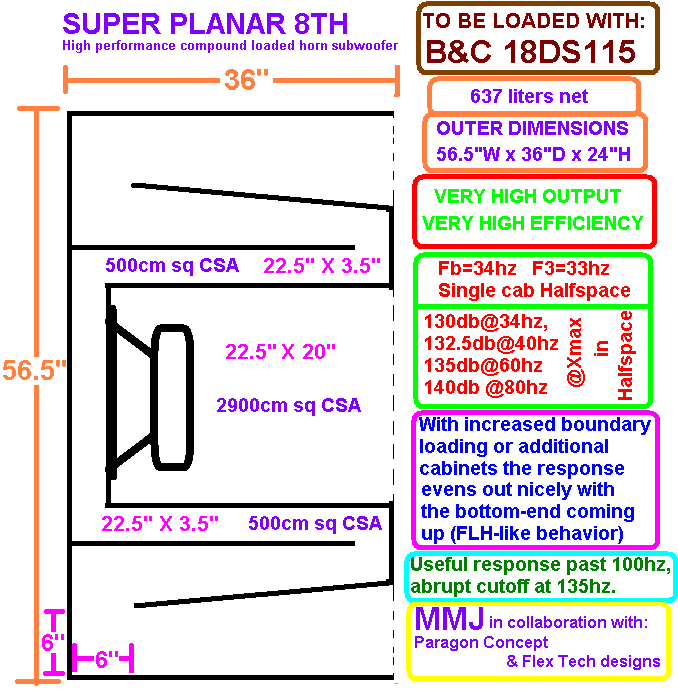
The Super Planar cabinet you have featured in the spreadsheet is at 60cm depth , that is why it tuned a little bit high (which is good in some cases, with lesser drivers) .... For strong 18" drivers like the 18DS115 or iPAL 18 we can go with the 90cm depth for the lower tuning and longer path length ....
Now i really need to update my Excel so i can run this xlsm file! Hehehe ..
Sir, your work is motivational!
It even automatically produces a cutsheet!
Last edited:
BP1fan ,
The approach in your sketch may work for you 🙂 .... The driver closest to the 180 degree turn will have the least loading, so i would expect it to be the first to run out of excursion ...
Your model currently isn't accurate though because your voicecoil inductance will need to come up to at least 3mh or more ..... It is a car audio driver so expect the inductance to be fairly high ... . For that 6 ohm Re , expect your inductance to be in the 3mh to 6mh range ...
Also be sure to engage the "Lossy Le" function in Hornresp for a more accurate model when using drivers such as this ...... I use "Lossy Le" in all of my models for the sake of accuracy, or at least conservative results (meaning not optimistic at all) ....
Make these changes and you will see that your curve is altered , but it is a more accurate representation of what you will really get in the real-world 🙂 So optimize accordingly ...
That work laptop does not have the option to upgrade HR. I want to say it's version 38 or 39.x.
Yeah, the website didn't provide inductance.
I'll model the enclosure on 1 of my home computers.
Talking about bugs, in troubleshooting this, I think I ran into a bug with Hornresp. Using F6 to refresh the import in the "Loudspeaker Wizard" apparently doesn't change the value of S6 to match what's in the current import file.
Hi Brian,
Further to my Post #748, could you please post a copy of a data file exported from boxplan-splanar.xlsm so that I can import it into Hornresp for testing purposes. Alternatively, simply post an xls version of your boxplan-splanar worksheet and I can export the test data myself. Many thanks.
Kind regards,
David
Hi David, I've attached a zip file containing the workbook in both versions of Excel. It also contains a few bug-fixes, one pretty major, so it should be used in place of the previous versions.
Attachments
Hi David, I've attached a zip file containing the workbook in both versions of Excel. It also contains a few bug-fixes, one pretty major, so it should be used in place of the previous versions.
Excellent, thanks Brian.
I never allowed for the possibility of a compound horn design being imported into the Loudspeaker Wizard.
When I get a chance I will have a look at what can be done to hopefully fix the problem.
The problem has been fixed in the latest release:
http://www.diyaudio.com/forums/subwoofers/119854-hornresp-801.html#post5308950

Hi David, I've attached a zip file containing the workbook in both versions of Excel. It also contains a few bug-fixes, one pretty major, so it should be used in place of the previous versions.
AWESOME STUFF BRIAN!
Thank you so very much for making this .....
and that is good news on the two options for excel files, i will give the new one a try now 🙂
Working with Brian's super cool Boxplan spreadsheets
Ok ,
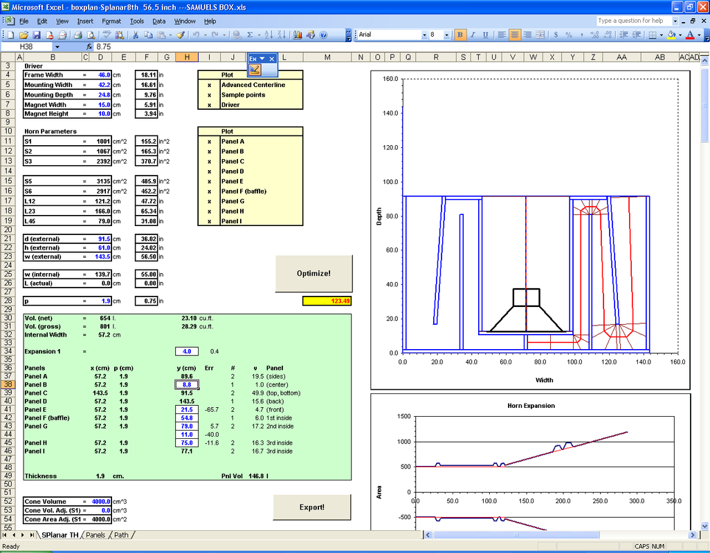
Brian after working with your awesome Boxplanner (should i call it a software or spreadsheet?) for the Super Planar 8th compound horn i believe i have it adjusted pretty closely to the flared option sketch seen in post #704
NOTE: Hornresp's "CH" mode works well here for this split-path symmetrical layout because there is no driver offset 🙂 If someone wanted to simulate the single path version of this cabinet it can easily be done in "OD" mode by utilizing the "rear vented" chamber option to form the high-tuned resonator section .. 😀
This "Boxplan" calculator is INCREDIBLY useful! =D
Here is the Sketch for the Super Planar 8th 56.5" intended to be loaded with B&C 18DS115 ... It correlates closely with the Boxplan file attached to this post .. .
Below i will paste the Hornresp code that was generated by the Boxplan , but it did not include the activation of "Lossy Le" (whatever switch in the code that is) so i ran it through my Hornresp with the "Lossy Le" enabled and this is the code that resulted as an export file :
ID=42.00
Ang=2.0 x Pi
Eg=113.14
Rg=0.00
Fta=2.64
S1=1001.00
S2=1067.00
Par=121.20
F12=0.00
S2=1067.00
S3=2392.00
Par=166.00
F23=0.00
S3=0.00
S4=0.00
L34=0.00
F34=0.00
S5=3134.56
S6=2917.20
Par=79.00
F56=0.00
Sd=1210.00
Bl=39.61
Cms=8.05E-05
Rms=15.33
Mmd=325.41
Le=3.85
Re=5.00
CH=1.00
Vrc=0.00
Lrc=0.00
Ap1=0.00
Lp=0.00
Vtc=4000.00
Atc=1210.00
Pmax=2000
Xmax=16.5
Path=0.0
Mass=0.00
Fr1=0.00
Fr2=0.00
Fr3=0.00
Fr4=0.00
Tal1=100
Tal2=100
Tal3=100
Tal4=100
Comment=BOXPLAN-Export (7.2 Beta)
~~~~~~~~~~~~~~~~~~~~~~~~~~~~~~~~~~~~~~~~~~~~~~~~~~~~~~~~~~~~~~~~~~~~~~~~~~~~~~~~~~~~
FILTER
0 0.01 0.0 -1 0 0.01 0.0 -1 0 0.01 0.0 -1
0 0.01 0.0 -1 0 0.01 0.0 -1 0 0.01 0.0 -1
100 25 0 0
40.50.50.5
0.50.50.50.5
SSSS
1111
1111
2222
1111
111
000
~~~~~~~~~~~~~~~~~~~~~~~~~~~~~~~~~~~~~~~~~~~~~~~~~~~~~~~~~~~~~~~~~~~~~~~~~~~~~~~~~~~~
NOTE: S5 is inflated for some reason even though it should be the same or less than S6 (to compensate for the volume that the driver's motor occupies) ...It is almost as if S5 and S6 are reversed? They are linked though and i cannot find the option to adjust them independently of one another .....
It would also be great to have the option to enable "Lossy Le" from within the Boxplan spreadsheet/software .. .... The 18DS115 looks really wonky in this box without that feature .. .
What do you think Brian?
Ok ,
Brian after working with your awesome Boxplanner (should i call it a software or spreadsheet?) for the Super Planar 8th compound horn i believe i have it adjusted pretty closely to the flared option sketch seen in post #704
NOTE: Hornresp's "CH" mode works well here for this split-path symmetrical layout because there is no driver offset 🙂 If someone wanted to simulate the single path version of this cabinet it can easily be done in "OD" mode by utilizing the "rear vented" chamber option to form the high-tuned resonator section .. 😀
This "Boxplan" calculator is INCREDIBLY useful! =D
Here is the Sketch for the Super Planar 8th 56.5" intended to be loaded with B&C 18DS115 ... It correlates closely with the Boxplan file attached to this post .. .
Below i will paste the Hornresp code that was generated by the Boxplan , but it did not include the activation of "Lossy Le" (whatever switch in the code that is) so i ran it through my Hornresp with the "Lossy Le" enabled and this is the code that resulted as an export file :
ID=42.00
Ang=2.0 x Pi
Eg=113.14
Rg=0.00
Fta=2.64
S1=1001.00
S2=1067.00
Par=121.20
F12=0.00
S2=1067.00
S3=2392.00
Par=166.00
F23=0.00
S3=0.00
S4=0.00
L34=0.00
F34=0.00
S5=3134.56
S6=2917.20
Par=79.00
F56=0.00
Sd=1210.00
Bl=39.61
Cms=8.05E-05
Rms=15.33
Mmd=325.41
Le=3.85
Re=5.00
CH=1.00
Vrc=0.00
Lrc=0.00
Ap1=0.00
Lp=0.00
Vtc=4000.00
Atc=1210.00
Pmax=2000
Xmax=16.5
Path=0.0
Mass=0.00
Fr1=0.00
Fr2=0.00
Fr3=0.00
Fr4=0.00
Tal1=100
Tal2=100
Tal3=100
Tal4=100
Comment=BOXPLAN-Export (7.2 Beta)
~~~~~~~~~~~~~~~~~~~~~~~~~~~~~~~~~~~~~~~~~~~~~~~~~~~~~~~~~~~~~~~~~~~~~~~~~~~~~~~~~~~~
FILTER
0 0.01 0.0 -1 0 0.01 0.0 -1 0 0.01 0.0 -1
0 0.01 0.0 -1 0 0.01 0.0 -1 0 0.01 0.0 -1
100 25 0 0
40.50.50.5
0.50.50.50.5
SSSS
1111
1111
2222
1111
111
000
~~~~~~~~~~~~~~~~~~~~~~~~~~~~~~~~~~~~~~~~~~~~~~~~~~~~~~~~~~~~~~~~~~~~~~~~~~~~~~~~~~~~
NOTE: S5 is inflated for some reason even though it should be the same or less than S6 (to compensate for the volume that the driver's motor occupies) ...It is almost as if S5 and S6 are reversed? They are linked though and i cannot find the option to adjust them independently of one another .....
It would also be great to have the option to enable "Lossy Le" from within the Boxplan spreadsheet/software .. .... The 18DS115 looks really wonky in this box without that feature .. .
What do you think Brian?
Attachments
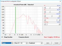
I tried to compare with and without lossy Le.
The following paramaters are changed:
Before:
SSSS
1111
1111
2222
1111
111
000
After:
SSSS
0111
1111
2222
1111
111
000
The parameter for enabling/disabling Le is 0111 off, and 1111 on
The following paramaters are changed:
Before:
SSSS
1111
1111
2222
1111
111
000
After:
SSSS
0111
1111
2222
1111
111
000
The parameter for enabling/disabling Le is 0111 off, and 1111 on
Last edited:
NOTE: S5 is inflated for some reason even though it should be the same or less than S6 (to compensate for the volume that the driver's motor occupies) ...It is almost as if S5 and S6 are reversed? They are linked though and i cannot find the option to adjust them independently of one another .....
Yeah, that looks like a bug. S5 should be the same as S6 as I've included no compensation for the volume taken up by the driver's magnet structure. I'll check the workbook this afternoon - should be a simple bug to sort out. They're both calculated values, set by the dimensions you choose for the box and the dimensions of the internal panels.
It would also be great to have the option to enable "Lossy Le" from within the Boxplan spreadsheet/software .. .... The 18DS115 looks really wonky in this box without that feature .. .
That might be difficult to do, as I'm using an earlier version of the Hornresp data file for import purposes as I couldn't get the workbook to work with the later version of the import file. However, once enabled in Hornresp, re-importing the Boxplan-created file shouldn't reset the "Lossy Le" option under Loudspeaker Wizard, so you can take the same approach I do with stuffing the horn (stuffing is also not included in the Boxplan export) - do a preliminary import, then under Loudspeaker Wizard set Lossy Le (and stuffing, if you're going to use that), tweak the layout in Boxplan and then use F6 to update Hornresp's Loudspeaker Wizard with newer versions of the Boxplan-created import files.
What do you think Brian?[/QUOTE]
Yeah, that looks like a bug. S5 should be the same as S6 as I've included no compensation for the volume taken up by the driver's magnet structure. I'll check the workbook this afternoon - should be a simple bug to sort out. They're both calculated values, set by the dimensions you choose for the box and the dimensions of the internal panels.
As I thought, it was a bug - the sample point for S5 was slightly incorrect. I've corrected it and uploaded the new version of the workbook to my website - http://www.diysubwoofers.org/sheets/beta/boxplan-splanar.zip
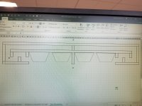
I also came up with an idea of a slightly different fold for this build - this fold brings the mouths closer together and ensures that all the external panels can be properly braced at their edges by other external panels. I've pictured it to the left of the original layout. It looks pretty close to the ROAR design, except the output isn't combined into one mouth.
Attachments
- Home
- Loudspeakers
- Subwoofers
- Compound loading 6th order quarterwave "Super Planar" horns and pipes concepts/builds