Paraflex with versatile driver options and versatile mouth placements
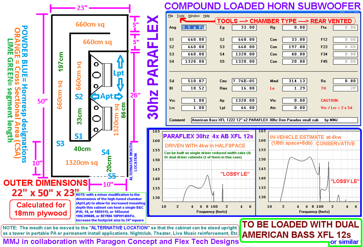
Adaptable Paraflex action, this one was designed to be loaded with American Bass brand XFL 12 drivers but with a minor modification it can host some PA drivers instead!
These Paraflex cabs are designed for a Mr Don B Paradox of Santa Cruz California ... We designed these cabinets to fit a pair into a Chevy Suburban without gobbling up all of the seating, so the cabinet could not be as LARGE as would be ideal but this compact version is a very good size/performance compromise ..

.... I particularly like the way the B&C 18DS115 and B&C iPAL 18 work in this box (with the dimensions of the high-tuned chamber altered to accommodate the increased mounting depth). .. For the right single 18" PA driver the box could be made 48" tall with a 24" square footprint with only minor adjustments to the layout such as shortening the high-tuned resonator chamber by just a few inches.. I can provide detail on that if anyone is curious ..
Adaptable Paraflex action, this one was designed to be loaded with American Bass brand XFL 12 drivers but with a minor modification it can host some PA drivers instead!
These Paraflex cabs are designed for a Mr Don B Paradox of Santa Cruz California ... We designed these cabinets to fit a pair into a Chevy Suburban without gobbling up all of the seating, so the cabinet could not be as LARGE as would be ideal but this compact version is a very good size/performance compromise ..
.... I particularly like the way the B&C 18DS115 and B&C iPAL 18 work in this box (with the dimensions of the high-tuned chamber altered to accommodate the increased mounting depth).
.. For the right single 18" PA driver the box could be made 48" tall with a 24" square footprint with only minor adjustments to the layout such as shortening the high-tuned resonator chamber by just a few inches.. I can provide detail on that if anyone is curious ..
Last edited:
Looks nice, but with only 1320 cm2 mouth area the air particle velocity must skyrocket at 4 kw?! If you watch the short videos I posted in the ROAR18 thread you can see the high air particle velocity of one single cheap 12 inch car audio driver in a 1500 cm2 frontresonator.
I believe Hornresp can't really simulate what happens at large velocities and high power in these kinds of straight section stepped designs. There seems to be a lot of potential gains from increased cross section area not seen in a sim. You probably need to use Comsol to simulate this.
I understand the need to keep the box size reasonable, but if your are aiming for mucho spl then I would recommend some more S5.
It is fun to follow your ideas and builds.
Cheers,
Johannes
with only 1320 cm2 mouth area the air particle velocity must skyrocket at 4 kw?
I understand the need to keep the box size reasonable, but if your are aiming for mucho spl then I would recommend some more S5.
Hello Johannes!
The 4kw is shared between 2 cabinets, so that means 2kw per cabinet, but i understand that is still quite a lot ........ This is all dependent upon whether or not the Chevy Suburban's electrical system can be upgraded enough and the right Class D amplifiers can all be made to happen for the right price ...... So i should say that according to Hornresp and the driver's published specifications one of these cabinets should handle 2kw, but whether they will actually be fed that much is another thing altogether 😉
Keeping the cabinet this small did require some compromises, if the cabinet were larger then i definitely would have made S5 larger ..........
Oddly enough (with this cabinet) opening up S5 is risky because at some point the lost loading at the chamber where the paths merge would result in new problems caused by the increased air particle velocity at S3 ..... I would be trading one problem for another ... In other words it is the loading in the chamber following S3 the helps keep the velocity at S3 from becoming excessive (in theory) ...... I see it as a "balancing act"...
There are only 2 Paraflex cabinets built and being used currently, so this is all new ....... One of the Paraflex cabinets contains a very heavy duty 15" high excursion driver being powered with between 2000 watts to 2500 watts and we didn't run into any noticeable air particle velocity issues with that one. In fact we were surprised to find out that the SPL exceeded our expectations (output was measured at beyond the anticipated 18db over halfspace which is our standard that we have been using as our "in-vehicle" prediction)... Apparently our method of predicting is conservative😱 , at least in some vehicles ........
In simulation Hornresp suggests that two of these cabinets in 1/8th space at full power will see air particle velocity of no more than 14 meters per second, at the mouth ... So according to Hornresp we are well within the safe range .....
It will be breezy for sure but as long as Hornresp didn't miscalculate by a large margin we should be alright 🙂
It is fun to follow your ideas and builds.
Cheers,
Johannes
Johannes, thank you! Good to hear that from innovative folks such as yourself
 .... I am following the ROAR discussion and it is great to see more builds happening!
 I did watch your recent videos with the Car Audio 12 , and i see what you mean, it does seem like there is a heck of a lot of air movement at the mouth despite the large mouth size ..... I am excited to see what that high excursion 15" driver will do in the ROAR
..... Looking forward to seeing more videos and measurements etc
Last edited:
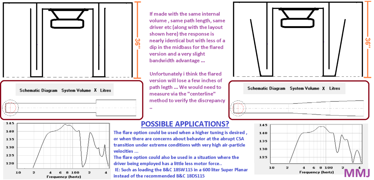
Had a request for some flare!
I received a request the other day from a gentleman who builds cabinets in the Dominican Republic , his name is Angel Romero ... He wanted me to add the flare mod to the 56" Super Planar 8th for the 18DS115 driver ... Here it is
..
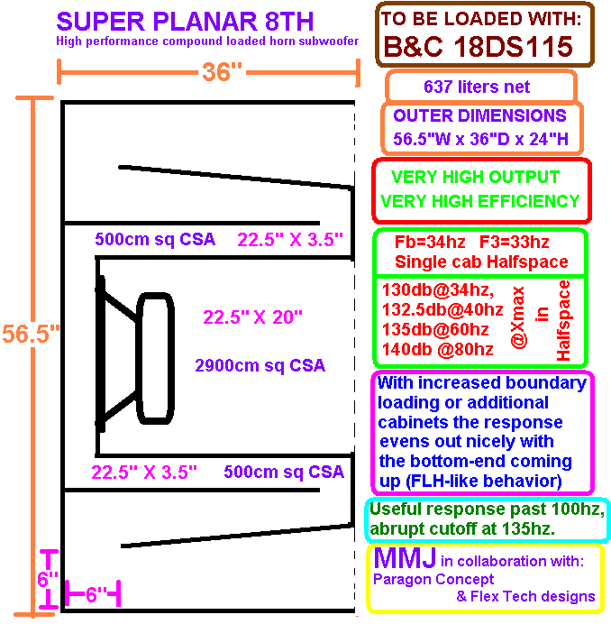
I had previously simulated the model with the flare versus without the flare in the image below.... I used the same drivers, same drive level, and same internal volume for a fair comparison... I was just curious to see how it would alter performance ... The differences between the two options were not remarkable (in sim) but it is nice to see a reduced severity of the midbass response hole ..🙂
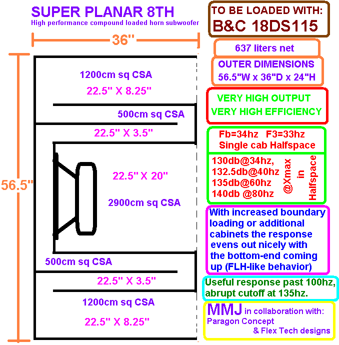
NOTE: J Vansickle is currently building some Super Planar 8th subs based on this layout (without the flare) .... With the 56" dimension scaled up to 77" , he wanted to make something truly massive for this nightclub install that he is working on .... 4 of these very large Super Planar 8th subs will be used in this nightclub system .. ........ I will be posting build photos as soon as tomorrow!
I received a request the other day from a gentleman who builds cabinets in the Dominican Republic , his name is Angel Romero ... He wanted me to add the flare mod to the 56" Super Planar 8th for the 18DS115 driver ... Here it is
An externally hosted image should be here but it was not working when we last tested it.
=)..
I had previously simulated the model with the flare versus without the flare in the image below.... I used the same drivers, same drive level, and same internal volume for a fair comparison... I was just curious to see how it would alter performance ... The differences between the two options were not remarkable (in sim) but it is nice to see a reduced severity of the midbass response hole ..🙂
NOTE: J Vansickle is currently building some Super Planar 8th subs based on this layout (without the flare) .... With the 56" dimension scaled up to 77" , he wanted to make something truly massive for this nightclub install that he is working on .... 4 of these very large Super Planar 8th subs will be used in this nightclub system .. ........ I will be posting build photos as soon as tomorrow!
Last edited:
UPDATE: Original spanned driver style Super Planar wideband kickbin horn top sketch
Here is the recently updated sketch for the spanned driver style Super Planar tops (compound loaded horn wideband kickbin) as seen in Post#1...... "Spanned" meaning both drivers share the same main path , at different offsets .... Dimensions calculated for 1/2" ply ..
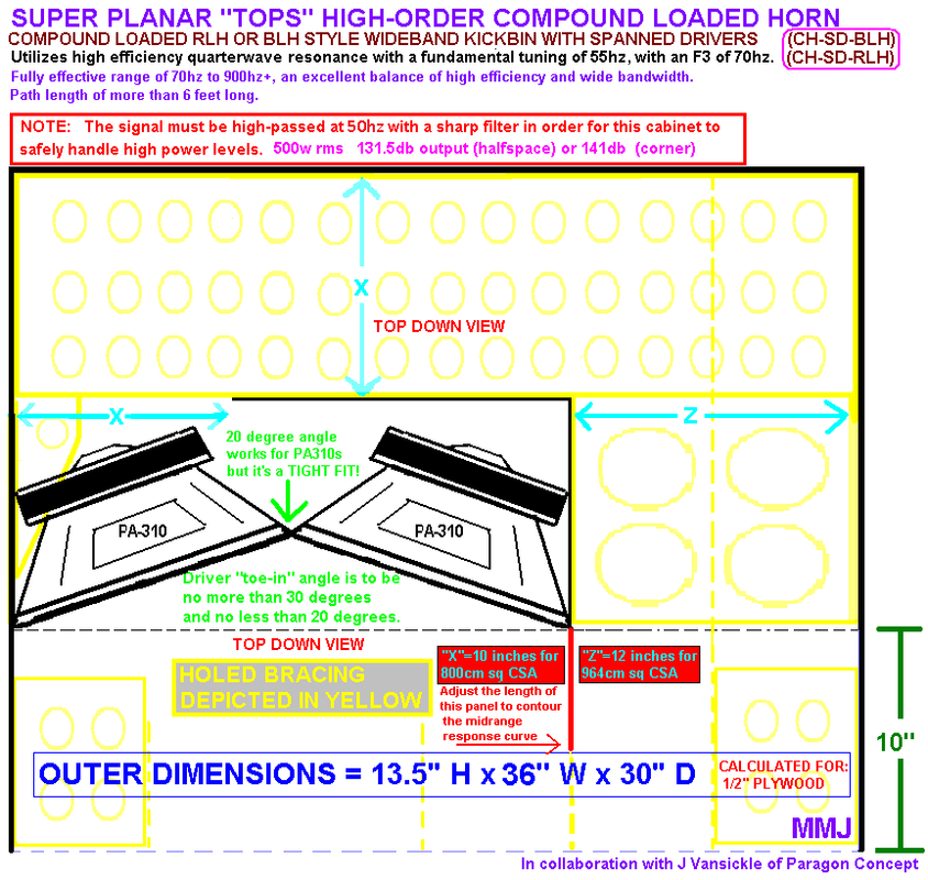
When using Dayton PA310 drivers in this cabinet the F3 is considerably higher than the Fb by a large margin according to Hornresp (specifics are mentioned in the text above the sketch) .... Using drivers with more motor force will bring the F3 lower .....
You could also modify this cabinet by using a straight baffle and a single 15" driver (the 13.5" outer dimension would need to be increased by about 3 inches).. ........ You could even make the cabinet slightly trapezoidal to be stood up on end and used in multiples as a splayed array (sitting on top of grouped subs in a PA stack for example) .....
There are lots of possibilities here 🙂
Here is the recently updated sketch for the spanned driver style Super Planar tops (compound loaded horn wideband kickbin) as seen in Post#1...... "Spanned" meaning both drivers share the same main path , at different offsets .... Dimensions calculated for 1/2" ply ..
When using Dayton PA310 drivers in this cabinet the F3 is considerably higher than the Fb by a large margin according to Hornresp (specifics are mentioned in the text above the sketch) .... Using drivers with more motor force will bring the F3 lower .....
You could also modify this cabinet by using a straight baffle and a single 15" driver (the 13.5" outer dimension would need to be increased by about 3 inches).. ........ You could even make the cabinet slightly trapezoidal to be stood up on end and used in multiples as a splayed array (sitting on top of grouped subs in a PA stack for example) .....
There are lots of possibilities here 🙂
Last edited:
Forces and reflections unto those 2 cones will be very different.
This will lead to phase issues,... peaks and cancellations.
... I think.
This will lead to phase issues,... peaks and cancellations.
... I think.
Forces and reflections unto those 2 cones will be very different.
This will lead to phase issues,... peaks and cancellations.
... I think.
Globalplayer ,
A set of these have already been built (take a look at post#1 of this discussion) ....
The builder loved the sound of them, and he said the cone control was excellent .... According to his reports the cones barely moved even when driving the cabinet with enough power to get very loud , he seemed impressed by this .....
He had fun with them at his house for a bit with a lot of listening tests before he hauled them off the nightclub to install them ... 🙂
Last edited:
The builder loved the sound of them, and he said the cone control was excellent .... According to his reports the cones barely moved even when driving the cabinet with enough power to get very loud , he seemed impressed by this .....
Sure.
OK.
But...
even if the design is "perfect" there will be tolerances between 2 "identical" speakers which lead to "uneven" cone movement between those 2 speakers and the consequences thereof.
Now if you additionally "load" them "uneven" because of enclosure design it will even get worse.
Then if the "load" on the cone itself is not symmetrical it will lead to increased partial movement of the cone itself (distortion) and can also lead to premature failure of the driver.
Generally it's better to put each speaker in a seperate enclosure.
This will also minimize the effects of tolerances.
Then if 1 speaker fails the other one will provide at least "1/2" of the spl.
If 2 speakers play into one/the same volume/enclosure and 1 speaker fails the whole enclosure will be (almost) useless.
How are you simulating that paraflex design again? It looks like it should be simulated as a compound horn, but the schematics you've posted suggest that you're using another method. If it was being sim'd as a compound horn, the schematic would look something like the attached image.
If I have some time today, I'll see if I can put together a workbook to sim the fold and work out the path length via the Advanced Centerline Method.
If I have some time today, I'll see if I can put together a workbook to sim the fold and work out the path length via the Advanced Centerline Method.
Attachments
How are you simulating that paraflex design again? It looks like it should be simulated as a compound horn, but the schematics you've posted suggest that you're using another method. If it was being sim'd as a compound horn, the schematic would look something like the attached image.
Brian ,
The Paraflex cabinet and the Super Planar 8th are both compound horns with the difference being that the Paraflex has it's paths merge at the very end , and a mouth is shared by both the high-tuned and low-tuned paths..
So the Paraflex is modeled in TH mode using the "Rear Vented" chamber option (Vrc/Lrc & Apt/Lpt are in play) to form the high-tuned chamber , the end of which taps into the main path very near the mouth ...
The Super Planar 8th on the other hand can be modeled in either "CH" mode or in "OD" mode utilizing the Rear Vented chamber option again as we did with the Paraflex except that it doesn't ever tap into the low-tuned path at all , it just stays separate and has it's own dedicated mouth .. .
The "OD" method has the advantage of allowing some driver-offset as we would have in the single-path layouts , or we can go with no offset as we would have with the split-path symmetrical layout ...... "CH" is limited to no driver-offset at all .. ... So "OD" mode is a little more versatile in that regard when modeling a Super Planar ....
If I have some time today, I'll see if I can put together a workbook to sim the fold and work out the path length via the Advanced Centerline Method.
Super Cool!
I have export files, and input screenshots etc for you, if you want .... I could send you examples of both Paraflex and Super Planars to load into your Hornresp 🙂
Generally it's better to put each speaker in a seperate enclosure.
This will also minimize the effects of tolerances.
Then if 1 speaker fails the other one will provide at least "1/2" of the spl.
Globalplayer,
The Super Planar symmetrical split-path style tops can be set up that way , basically two cabinets built into one and each main path can be dedicated to a single driver . 🙂
Brian ,
The Paraflex cabinet and the Super Planar 8th are both compound horns with the difference being that the Paraflex has it's paths merge at the very end , and a mouth is shared by both the high-tuned and low-tuned paths.. <snip>
You should probably show the input screen with every design.
I guess all BP6's are compound horns.
TH & Paraflex = series tuned flared or non flared compound horn.
Super Planar = parallel tuned flared compound horn or non flared BP6.
Where does the 8th order come in on the Super Planar?
Not exactly , no .. .
BP6 is compound loaded but not a compound horn because there is no quarterwave loading with a classic BP6 .. .
A TH is not compound loaded because it is lacking the additional chamber/resonator required to be compound loaded ...
BP1FAN, The "8th order" thing is just what we used to label the cabinets that function effectively as an 8th order because they have enough expansion in the main path to shift the FbX3 harmonic all the way down to to below the high-tuned resonators frequency ...... The effect is easy to spot with the original Super Planar 8th style but in our Paraflex variant the high tuned resonator's output and the shifted FbX3 end up being more lumped together as one big fat resonance ..
Last edited:
You should probably show the input screen with every design.
BP1Fan,
Sometimes i do , but not always ..... Is there any in particular that you would like to see? I can share export files and input page screenshots etc ... Just let me know!
Not exactly , no .. .
BP6 is compound loaded but not a compound horn because there is no quarterwave loading with a classic BP6 .. .
A TH is not compound loaded because it is lacking the additional chamber/resonator required to be compound loaded.
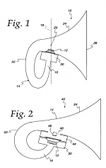
Tom Danley's tapped horn patent has a compression chamber.
Attachments
Tom Danley's tapped horn patent has a compression chamber.
BP1Fan ,
The old drawing does show compression chambers (on both sides of the driver even!) but I don't believe Danley ever built them that way (not that i am aware) and in order for that throat chamber to develop it's own resonance within the passband of a subwoofer it would have to be sizeable... Just look at the size of the chamber we are using for the Paraflex (in relation to the rest of the box) , that is what it took to develop a resonance at the top of the subwoofer's passband , and also helps to define the upper cutoff .. .
BP1Fan , I have some really good news i am about to post here in a few minutes
...... We just found an affordable Car Audio sub driver which has Parameters that work remarkably well in a compact Paraflex , and these parameters are verified with measurement as of yesterday evening! 😀Waiting!.....
Johannes , this driver should work in a ROAR as well !

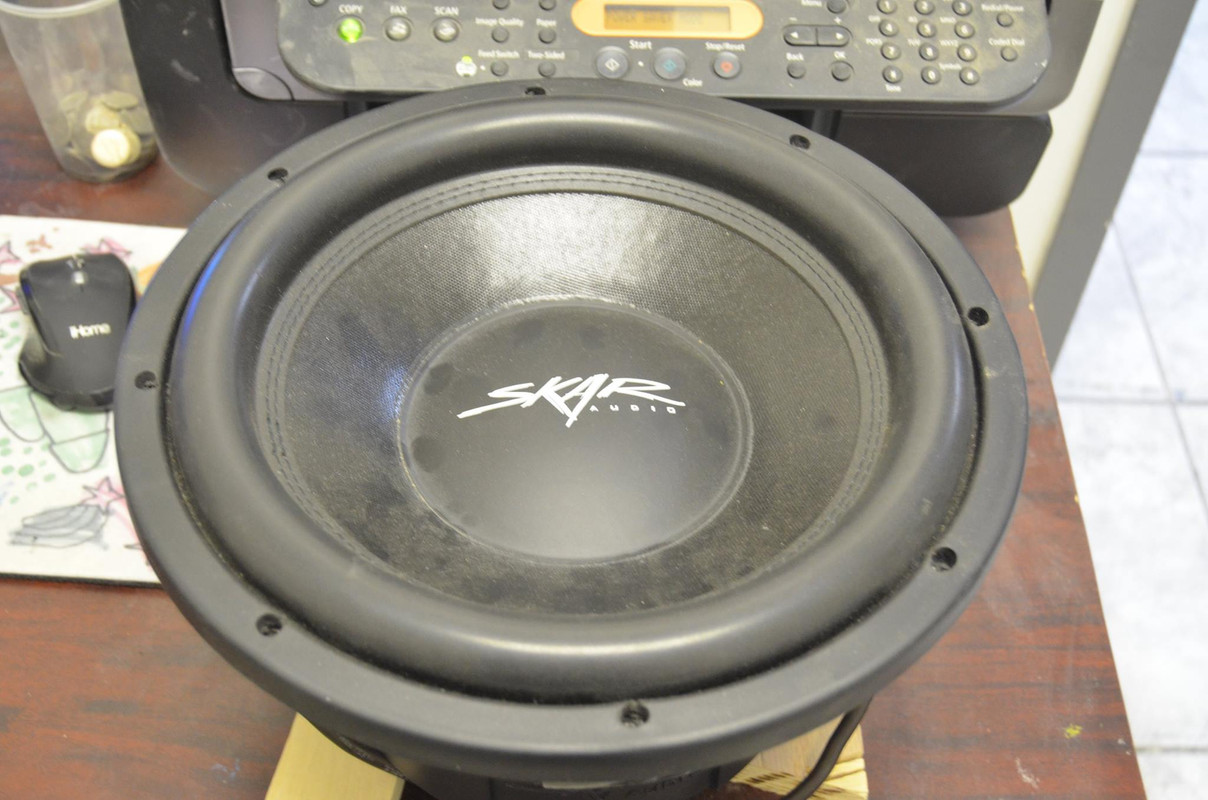
SKAR DDX 12" measured parameters ... MARVELOUS FOR PARAFLEX , SUPER PLANAR 8TH Etc
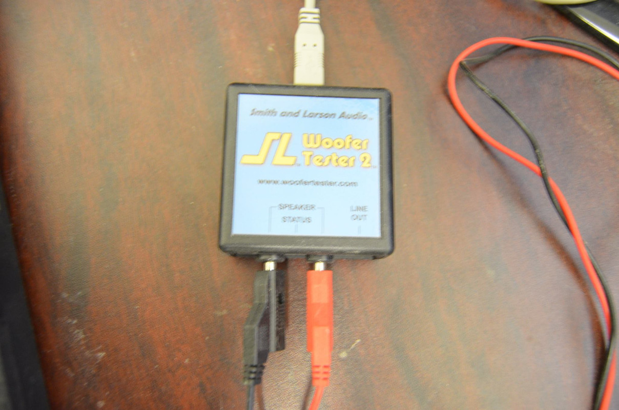
J R Vansickle of Paragon Concept in North Carolina owns a Smith & Larson Woofertester2 unit and has been measuring drivers lately ..
Yesterday he measured a truly remarkable driver ... It is the Skar Audio brand DDX 12 , and we have some very exciting news to report!
The measured Parameters are extraordinarily suitable for our high-order cabinets like the Paraflex and the Super Planar 8th!!!😀 (and i imagine it would also work well in a ROAR) .....
This is such a breath of fresh air after all of the disappointments we have experienced with Car Audio drivers lately🙄...
NOTE: The DDX 12 is most appropriate for cabinets tunings in the 33hz to 40hz range (the suspension is extremely tight , low compliance , so tuning far below the driver's Fs value is not really an option , Group Delay becomes an issue)
Ok guys , here they are:
Measured by J Vansickle of Paragon Concept
SKAR DDX 12" D2 (broken in)
Jan 7th 2018
Re = 0.9790 ohms
Fs = 38.4740 Hz
Zmax = 15.7128 ohms
Qes = 0.3420
Qms = 5.1471
Qts = 0.3207
Le = 1.0710 mH (at 1 kHz)
Diam = 254.0000 mm ( 10.0000 in )
Sd = 50670.7504 mm^2( 78.5398 in^2)
Vas = 22.2787 L ( 0.7868 ft^3)
BL = 13.9235 N/A
Mms = 280.1522 g
Cms = 61.0817 uM/N
Kms = 16371.5244 N/M
Rms = 13.1576 R mechanical
Efficiency = 0.3486 %
Sensitivity= 87.4414 dB @1W/1m
Sensitivity= 96.5646 dB @2.83Vrms/1m
Krm = 5.142E-03 ohms Freq dependent resistance
Erm = 721.087E-03 Rem=Krm*(2*pi*f)^Erm
Kxm = 22.562E-03 Henries Freq dependent reactance
Exm = 655.496E-03 Xem=Kxm*(2*pi*f)^Exm
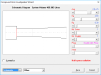
Here is a quick simulated Paraflex curve (below) .... I will post more detailed sims and curves in the near future as I put them together ..
This is two of the DDX 12s in a 210-ish liter 35hz tuned Paraflex using the "Lossy Le" mode in Hornresp ..... Driven to around the Xmax rating , maybe slightly over by 1mm or two , still in the very safe range🙂 ... ...
It is the estimated "in-vehicle" response which isn't quite 18db over Halfspace , and we are finding that this method is conservative .. 😀
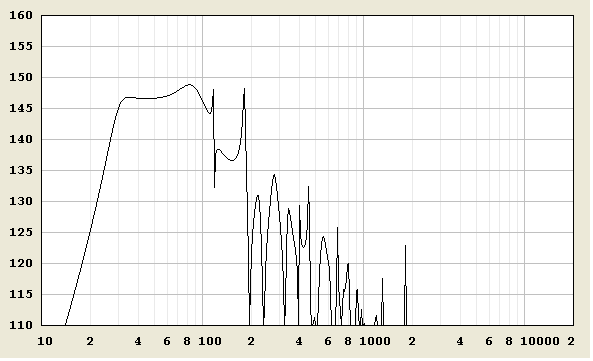
If anyone is curious about the output in HALFSPACE I can tell you that two of these drivers in the 35hz tuned 210-ish liter cabinet produces about 130db at full power , and has solid response right down to 35hz , upper limits would probably be at least around 90hz before response starts to dwindle above that .............................. To put things into perspective it is nearly impossible to find a 18" PA driver for $320 that can match this output and extension in a 200 liter quarterwave loaded cabinet ....... PA 18s that are capable of this are usually much more expensive than $320 ...
Two of the DDX 12s can displace about as much air as an 18" driver with 15mm of linear one-way cone travel and has a combined power handling of 2000w RMS ..
SKAR DDX 12
WELL DONE SKAR!!! BRAVO!!!
J R Vansickle of Paragon Concept in North Carolina owns a Smith & Larson Woofertester2 unit and has been measuring drivers lately ..
Yesterday he measured a truly remarkable driver ... It is the Skar Audio brand DDX 12
, and we have some very exciting news to report! The measured Parameters are extraordinarily suitable for our high-order cabinets like the Paraflex and the Super Planar 8th!!!😀 (and i imagine it would also work well in a ROAR) .....
This is such a breath of fresh air after all of the disappointments we have experienced with Car Audio drivers lately🙄...
NOTE: The DDX 12 is most appropriate for cabinets tunings in the 33hz to 40hz range (the suspension is extremely tight , low compliance , so tuning far below the driver's Fs value is not really an option , Group Delay becomes an issue)
Ok guys , here they are:
Measured by J Vansickle of Paragon Concept
SKAR DDX 12" D2 (broken in)
Jan 7th 2018
Re = 0.9790 ohms
Fs = 38.4740 Hz
Zmax = 15.7128 ohms
Qes = 0.3420
Qms = 5.1471
Qts = 0.3207
Le = 1.0710 mH (at 1 kHz)
Diam = 254.0000 mm ( 10.0000 in )
Sd = 50670.7504 mm^2( 78.5398 in^2)
Vas = 22.2787 L ( 0.7868 ft^3)
BL = 13.9235 N/A
Mms = 280.1522 g
Cms = 61.0817 uM/N
Kms = 16371.5244 N/M
Rms = 13.1576 R mechanical
Efficiency = 0.3486 %
Sensitivity= 87.4414 dB @1W/1m
Sensitivity= 96.5646 dB @2.83Vrms/1m
Krm = 5.142E-03 ohms Freq dependent resistance
Erm = 721.087E-03 Rem=Krm*(2*pi*f)^Erm
Kxm = 22.562E-03 Henries Freq dependent reactance
Exm = 655.496E-03 Xem=Kxm*(2*pi*f)^Exm
Here is a quick simulated Paraflex curve (below) .... I will post more detailed sims and curves in the near future as I put them together ..
This is two of the DDX 12s in a 210-ish liter 35hz tuned Paraflex using the "Lossy Le" mode in Hornresp ..... Driven to around the Xmax rating , maybe slightly over by 1mm or two , still in the very safe range🙂 ... ...
It is the estimated "in-vehicle" response which isn't quite 18db over Halfspace , and we are finding that this method is conservative .. 😀
If anyone is curious about the output in HALFSPACE I can tell you that two of these drivers in the 35hz tuned 210-ish liter cabinet produces about 130db at full power , and has solid response right down to 35hz , upper limits would probably be at least around 90hz before response starts to dwindle above that .............................. To put things into perspective it is nearly impossible to find a 18" PA driver for $320 that can match this output and extension in a 200 liter quarterwave loaded cabinet ....... PA 18s that are capable of this are usually much more expensive than $320 ...
Two of the DDX 12s can displace about as much air as an 18" driver with 15mm of linear one-way cone travel and has a combined power handling of 2000w RMS ..
SKAR DDX 12
WELL DONE SKAR!!! BRAVO!!!
Last edited:
- Home
- Loudspeakers
- Subwoofers
- Compound loading 6th order quarterwave "Super Planar" horns and pipes concepts/builds