Hi Art,
loving the 2 keystones I've built so far.
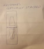
Question: see attached sketches - would there be a slight increase in summation / SPL if the horn exits were together as opposed to just vertically stacked?
I'm progressing and building another 2 for a total of 4, and adding waveguides for a mono stack.
I plan on tieing the bottom waveguides, of the stack, together with a box section of aluminum tube - as I believe the ground plane eliminates the need for another ply boundary.
Thoughts ? - cheers Art
I've tried just briefly laying my two Keystones down and they seem to loose a bit compared to standing up, of some reason.
Hi Mars,Question: see attached sketches - would there be a slight increase in summation / SPL if the horn exits were together as opposed to just vertically stacked?
I'm progressing and building another 2 for a total of 4, and adding waveguides for a mono stack.
I plan on tieing the bottom waveguides, of the stack, together with a box section of aluminum tube - as I believe the ground plane eliminates the need for another ply boundary.
The quad vertical stack would be taller, so the barn doors will have a larger area, providing slightly more forward gain than the mouth to mouth quad. The quad vertical stack would also have slightly more narrow vertical dispersion.
The quad vertical stack will not have symmetrical dispersion in the horizontal plane.
For a mono stack, I'd go for the symmetry of the mouth to mouth quad over the slight gain of the quad vertical stack- plus it's a lot easier to stack ;^).
Not exactly sure what you mean writing "the ground plane eliminates the need for another ply boundary".
An additional boundary below and/or above the stack would further increase forward gain, though an additional boundary below would require lifting the subs on to scaffold, difficult (and unsafe) without a large platform.
Art
I've tried just briefly laying my two Keystones down and they seem to loose a bit compared to standing up, of some reason.
thanks, I intend to measure a few different configs ..
Hi Mars,
The quad vertical stack would be taller, so the barn doors will have a larger area, providing slightly more forward gain than the mouth to mouth quad. The quad vertical stack would also have slightly more narrow vertical dispersion.
The quad vertical stack will not have symmetrical dispersion in the horizontal plane.
For a mono stack, I'd go for the symmetry of the mouth to mouth quad over the slight gain of the quad vertical stack- plus it's a lot easier to stack ;^).
Not exactly sure what you mean writing "the ground plane eliminates the need for another ply boundary".
An additional boundary below and/or above the stack would further increase forward gain, though an additional boundary below would require lifting the subs on to scaffold, difficult (and unsafe) without a large platform.
Art
Thanks, Art - what I was referring to was the bottom piece of plywood at the base of the stack that would make up the 4 sided waveguide - the ground would act as the boundary eliminating the need for the bottom piece of ply.
cheers
Mars,Thanks, Art - what I was referring to was the bottom piece of plywood at the base of the stack that would make up the 4 sided waveguide - the ground would act as the boundary eliminating the need for the bottom piece of ply.
cheers
My mistake, I didn't look at your side elevation drawing, and by the scale of the front view thought that you were planning to use 4'x8' plywood as "barn doors" directly left/right from the cabinet edges rather than "waveguides" at a 45 degree angle.
Replacing the bottom portion of the "waveguide" with an aluminum strut would work fine.
That said, my tests indicate the same amount of plywood used as "barn doors" would result in a bit more forward gain, and eliminate the strut and the top piece of plywood. Attachment with ratchet straps across the front and around the back would do the trick, and construction would be simplified.
Easy to test at low level with raw plywood sheets before you do any permanent bracing or attachment detail work.
If you do a comparison, please post the results.
Cheers,
Art
Hi Mars,
additional boundary below would require lifting the subs on to scaffold, difficult (and unsafe) without a large platform.
Art
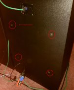
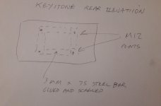
Ive installed 4 x M12 points at the back of the keystones, 75mm x 3mm plate steel with 4 x M12 extended nuts welded on. Linking cabinets together with a vertical mast and appropriate outriggers? ... not quite there yet. but that's the plan boss.
Yep will post measurements. Your measurements so far are in line with mine with the 18SW115- 4. The BnC 18SW you recommended was a wise choice... edit can't attach pic? fixed. Wait for upload,
Attachments
Last edited:
Mars,
My mistake, I didn't look at your side elevation drawing, and by the scale of the front view thought that you were planning to use 4'x8' plywood as "barn doors" directly left/right from the cabinet edges rather than "waveguides" at a 45 degree angle.
Replacing the bottom portion of the "waveguide" with an aluminum strut would work fine.
That said, my tests indicate the same amount of plywood used as "barn doors" would result in a bit more forward gain, and eliminate the strut and the top piece of plywood. Attachment with ratchet straps across the front and around the back would do the trick, and construction would be simplified.
Easy to test at low level with raw plywood sheets before you do any permanent bracing or attachment detail work.
If you do a comparison, please post the results.
Cheers,
Art
Attachments
View attachment 609997
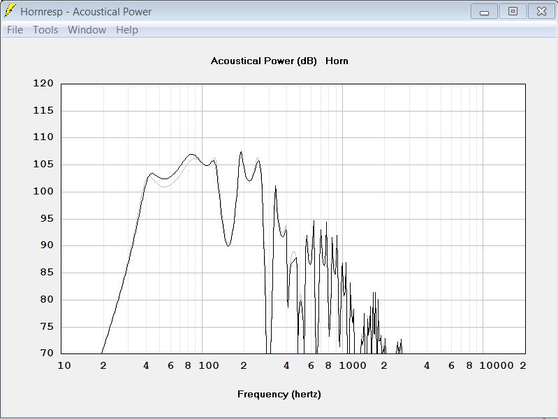
Here is a better balanced version of the resonator-enhanced THAM15.
A shorter resonator with larger cross-section.
It adds 7 dB efficiency at 80 Hz, the center of the midbass "kick".
Many THs have a dip in the response in the midbass, where you usually would want a small peak to accentuate the midbass "punch" and energy.
Thanks! I have built a ROAR12 and I like it a lot. I have not run it in any live venue. I hope I will get my MiniDSP and Umik tomorrow so I can take some measurements.
Cheers,
Johannes
Could you please elaborate a bit on this? What dimension would the resonator have? I compared the hornresp input with the original tham15 values, but i am not sure how to translate the difference into dimensions.
loving my thams btw <3
After a bit of correspondance with circlomanen, i decided to give the qwfrontresonator enhanced tham 15 a try.
From Post #119 and Post #143 and the private conversation i gathered the following:
The resonator is a simple box coupled to the horn mouth of the tham. the attached side is closed except for the horn mouth area. the other end is open.
According to the hornresp sim, the length of it would be 80cm. The according front area of the resonator should be between 3600cm² (grey curve) and 4800cm² (black curve)
The area does not have to be square but should stay inbetween 1:1 to 2:1 ratio.
The hornmouth-entrance should be as centered as possible in the resonator.
I thus decided to make it fit to the tham15 layed down on the side, building with the following dimensions:
500mm*964mm*800mm with 18mm wood.
This results in a front area of 464mm*928mm equals ~4306cm².
464mm is the width of the tham15 horn mouth, so this would make for a 2:1 atio, and the resonator also visually coupling to the subwoofer.
The mouths height is ~255mm. so, to have it centered the one end of the resonator would need to be closed with a sheet of 336mm*464mm on each side.
2x sheet of 464mm*800mm
2x sheet of 964mm*800mm
2x sheet of 464mm*336mm.
For the attachement, i plan on using simple locking bolts and a bit of gasket strip around the hornmouth.
going to buy wood later, stay tuned!
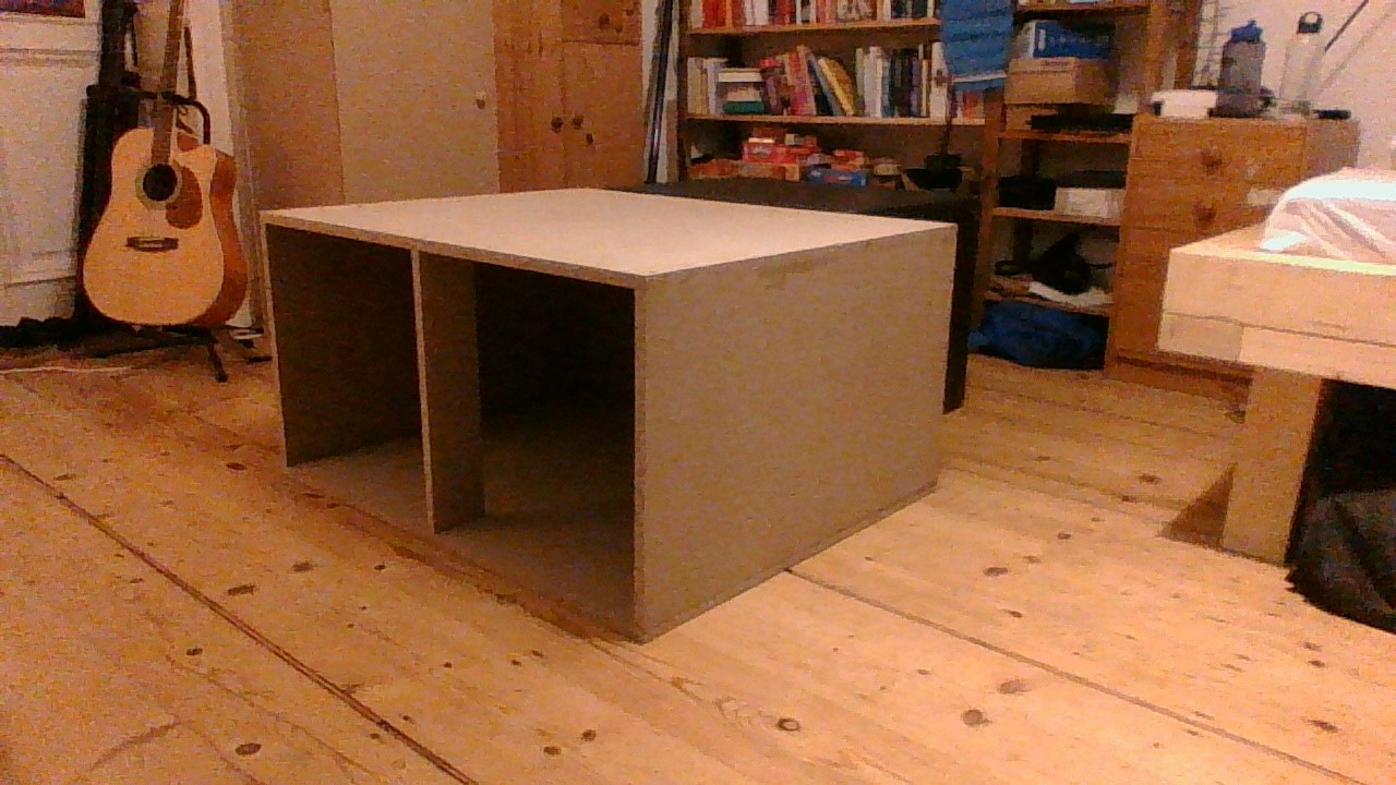
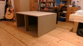
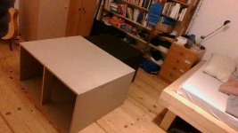
I finished the enclosure, added bracing for stability. It is quite big and heavy. Maybe I was a bit silly to have the wood cut first and then think about transport - almost dropped it on the 500m way from the metro to my house 
 hopefully i will find time this weekend to set the system up in the garden and do some measurements.
Attachments
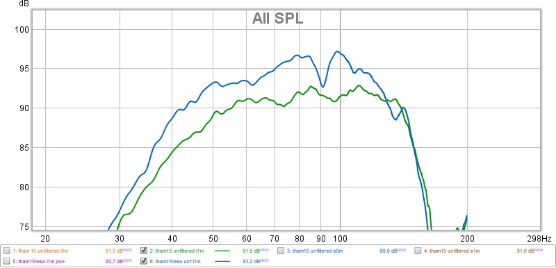
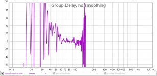
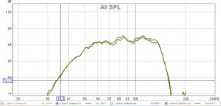
I set the THAM15 and the resonator up in the garden yesterday and tried to make some quick measurements. As a first result, the resonator seems to work. Subjectively, it boosts the bass quite noticeably, adds chest punch and a bit of character, the bass seems rougher. maybe "tactile" is the right word.
Not sure, how reliable the measurements are really, due to background noise and nearby walls (at 6 meters approx). I couldn't specify the voltage, so matching the curves by signal was a bit complicated. Will repeat together with a friend, who is an experienced semi-professional with better equipment.
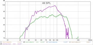
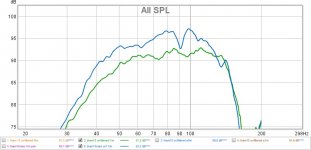
Driven at aprox. 1kw, the resonator enhanced THAM15 played against two of these Jobst JL-Sat10 tops. Not sure, if two resonator-enhanced THAMS wouldn't outplay them. Seems like I need stronger tops....
For now:
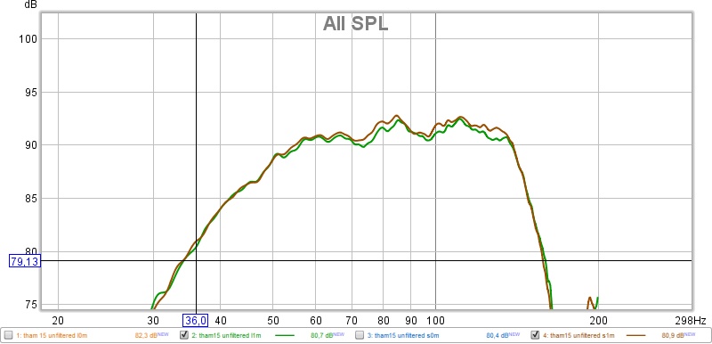
Measurements were taken using a miniDSP UMIK-1, without filters applied, at 0m and 1m distance, in standing and lying position, with and without the resonator (with resonator only in lying position).
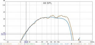
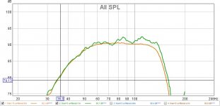
Standing at 0m (blue) vs. 1m (brown)
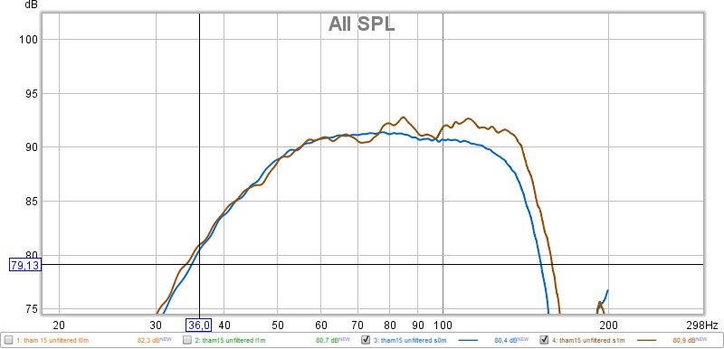

Lying at 0m vs. 1m:
Seems like in lying position it looses a little bit of power:
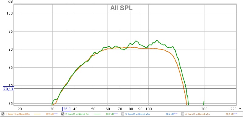
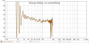
First measurement of the reso:
Weird notch at 90hz. Didn't make much difference at 0m, 1m and 3m. I was a bit disappointed. Resetup and measured again:
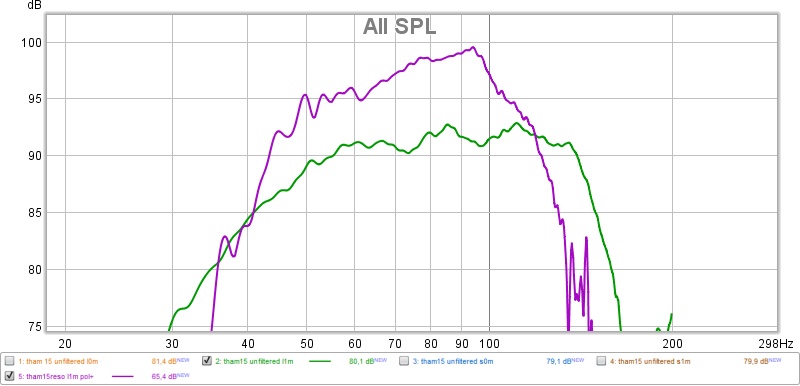
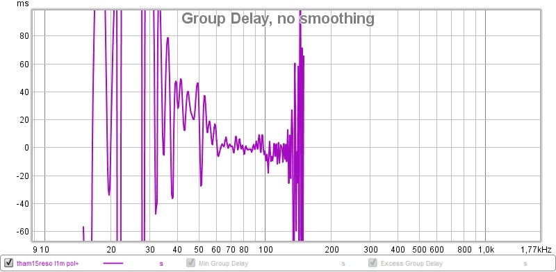
Not sure, were the notch went, but it didnt occur again. Any Ideas?
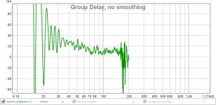
I am aware that this measurements can only serve as a starting point. Next up is better measurements, also in stacking.
Not sure, how reliable the measurements are really, due to background noise and nearby walls (at 6 meters approx). I couldn't specify the voltage, so matching the curves by signal was a bit complicated. Will repeat together with a friend, who is an experienced semi-professional with better equipment.
Driven at aprox. 1kw, the resonator enhanced THAM15 played against two of these Jobst JL-Sat10 tops. Not sure, if two resonator-enhanced THAMS wouldn't outplay them. Seems like I need stronger tops....
For now:
Measurements were taken using a miniDSP UMIK-1, without filters applied, at 0m and 1m distance, in standing and lying position, with and without the resonator (with resonator only in lying position).
Standing at 0m (blue) vs. 1m (brown)
Lying at 0m vs. 1m:
Seems like in lying position it looses a little bit of power:
First measurement of the reso:
Weird notch at 90hz. Didn't make much difference at 0m, 1m and 3m. I was a bit disappointed. Resetup and measured again:
Not sure, were the notch went, but it didnt occur again. Any Ideas?
I am aware that this measurements can only serve as a starting point. Next up is better measurements, also in stacking.
Attachments
-
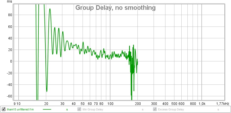
 THAM15RESO L1M GD.jpg78.3 KB · Views: 863
 -
 THAM15 vs THAM15RESO L1M.jpg68 KB · Views: 857
 -
 THAM15 RESO NOTCH.jpg63.2 KB · Views: 840
 -
 THAM15 S1M GD.jpg70.4 KB · Views: 1,246
 -
 THAM15 S0-1M.jpg61 KB · Views: 1,321
 -
 THAM15 LS1M.jpg59.2 KB · Views: 846
 -
 THAM15 L1M GD.jpg73.1 KB · Views: 869
 -
 THAM15 L0-1M.jpg60.2 KB · Views: 860
Last edited:
Thank you for making and posting the measurements of the front resonator enhanced THAM15, and thank you for your subjective impressions of its character.
I recognize the "tactile" part of its character. I love the punsch and physical energy of large front resonators.
Thanks!!
Johannes
I recognize the "tactile" part of its character. I love the punsch and physical energy of large front resonators.
Thanks!!
Johannes
Not sure, were the notch went, but it didnt occur again. Any Ideas?
Leakage between the THAM15 and the front resonator?
Phil,Next plan is some keystones with extenders as well ... our 4 x SS15's run out of steam way before our Unity horns. Time for something new.
Was looking over your "DiY HiFi" system, see you finished the Keystones, but saw no extenders on them.
Wondering if you have ever measured the SS15 with and without extenders along side the Keystone?
Art
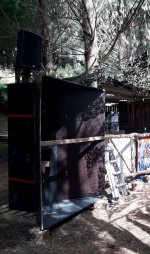
This was a Pre-covid - 2 x Keystones stacked vertically a side with large waveguides ... it sounded exceptional. Danley SM80's sitting on top of the beast. Plenty of punch!! and rear rejection behind the stacks - quite directional and it worked really well.... quite a bit of work bracing the waveguides but well worth it.
Cheers
Martin

Cheers
Martin
Attachments

Hi Art, only just seen this. No extenders for the keystones yet BUT we do have another pair to play with for the next gigs... so will try some different stacking configs to see what matches the SS15's bestPhil,
Was looking over your "DiY HiFi" system, see you finished the Keystones, but saw no extenders on them.
View attachment 1090861
Wondering if you have ever measured the SS15 with and without extenders along side the Keystone?
Art
.p.
Cool, Phil- looking forward to seeing how the sensitivity and LF extension compare.so will try some different stacking configs to see what matches the SS15's best
Art
Well ! I never managed to get a measurement mic out in anger ( as usual ran out of time) and the two outside keystones have RCF drivers compared to the inside B&Cs ( had to add very slight delays in the two different types of amps - pre-measured ) BUT a stack of 4 is pretty impressive ! Very directive in coverage as a central stack will do... worked well to make the area we were given work really well against other sounds close by.
4 upright Keystones seems to be the winner so far.
We also ran fully solar for this one even with the extra subs ( thnx Aussie sunshine!)

4 upright Keystones seems to be the winner so far.
We also ran fully solar for this one even with the extra subs ( thnx Aussie sunshine!)
Hi all!
I've been inspired by DIY Hi-Fi's photos of their horn extenders and wanted to make a set for my 30Hz modified tapped horns to make them more directional and increase SPL. The extender would be collapsable and be assembled and attached to the THs via the strap holes (for ratchet straps) and non-vibrational latches. I just wanted to seek feedback before following through with these plans.
The inner dimensions of the mouth are 109.2cm x 112.9cm and is 50cm deep with one side angled at 45deg. Side note, I unfortunately cannot run Hornresp because I own a mac so these dimensions aren't concrete or based in anything. Don't kill me haha


Let me know what you think, thanks!
I've been inspired by DIY Hi-Fi's photos of their horn extenders and wanted to make a set for my 30Hz modified tapped horns to make them more directional and increase SPL. The extender would be collapsable and be assembled and attached to the THs via the strap holes (for ratchet straps) and non-vibrational latches. I just wanted to seek feedback before following through with these plans.
The inner dimensions of the mouth are 109.2cm x 112.9cm and is 50cm deep with one side angled at 45deg. Side note, I unfortunately cannot run Hornresp because I own a mac so these dimensions aren't concrete or based in anything. Don't kill me haha
Let me know what you think, thanks!
Hiya...well I'm glad our " strap on" extenders got you inspired ! A few things that I would do given a Mkii version...
Firstly a horizontal brace as well as a vertical one , maybe latching in the centre for added rigidity. The large flat panels on the sides resonate at weird freqs! Last weekend we did a gig with multiple bands and for just that gig the kick drum would resonate through the subs at exactly 126hz ! Added a tight notch filter to the L R eq ...problem solved but it changes every gig with the room / space.
We added rubber window insulation strips to the edges of the extension panels so that when we use the latches they squeeze & seal with a vibration free joint. Next time around I would use a harder rubber product as the window stuff rips / tears too easily.
I would use the same latch system though.... only adding some kind of small plate behind the " male" end ... In the photo below it would be on the top / bottom panels.
Other than that they are over 10 years old and still going.... BUT they are also a prime target for gig graffitti artists !
- Home
- Loudspeakers
- Subwoofers
- Horn Extender/Wave-guide for TH