With today's music content and home theater systems, I can't believe people keep designing their SUBS to only reach to 40hz.
I need to dive into these. I want a HT sub say 70-20hz, maybe bragging rights for under 20hz. It will be nearfield and fire into the sofa. I want it kinda thin say like 6'x3'x1' or less deep. Any suggestions?
You might consider going thicker, the good drivers are 12" and 15".I need to dive into these. I want a HT sub say 70-20hz, maybe bragging rights for under 20hz. It will be nearfield and fire into the sofa. I want it kinda thin say like 6'x3'x1' or less deep. Any suggestions?
Was thinking about getting creative and face mount t line or multi sealed. Not sure. Was planning IB but new to near field.
Getting to know Boxplan-MTH
Hi Brian,
Since you suggested I try your amazing box calculators I've been practicing. 🙂
I am trying to model a Tapped Horn box for the Alpine R-W12D2 with the LAB12 design here at DIY Audio.
My idea is that I'd start with the LAB12 design as a baseline, then optimise the TH box for the Alpine using the iterative steps described in this thread at post #245.
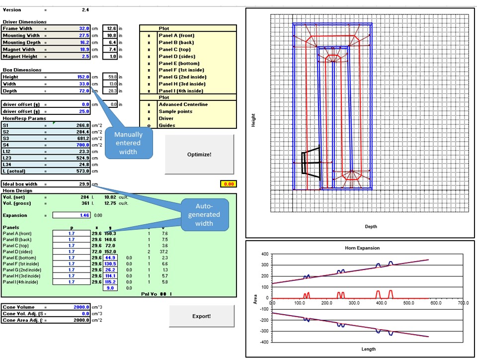
My stumbling block has been that even though I enter the driver frame width as 32cm and the enclosure internal width dimension as 33cm, I get an auto calculated ideal box width of 29.9cm and internal panel width as 29.6cm.
This means my driver won't fit in the box. 😕
I am sure this is just a case of beginners luck, so hoping for some help please!
Hi Brian,
Since you suggested I try your amazing box calculators I've been practicing. 🙂
I am trying to model a Tapped Horn box for the Alpine R-W12D2 with the LAB12 design here at DIY Audio.
My idea is that I'd start with the LAB12 design as a baseline, then optimise the TH box for the Alpine using the iterative steps described in this thread at post #245.
My stumbling block has been that even though I enter the driver frame width as 32cm and the enclosure internal width dimension as 33cm, I get an auto calculated ideal box width of 29.9cm and internal panel width as 29.6cm.
This means my driver won't fit in the box. 😕
I am sure this is just a case of beginners luck, so hoping for some help please!
Attachments

Last edited:
The value that you enter under "Width" is your desired EXTERNAL width of the box. The spreadsheet will calculate the internal width based on the value you provide for the external width and for the thickness of the panels. Note that you currently have that thickness at 1.7 cm - if using 3/4 ply, the thickness will be closer to 1.9 cm.
The "ideal box width" is the width that would be required to keep the mouth of the TH square, based on the value that you entered for S4.
The "ideal box width" is the width that would be required to keep the mouth of the TH square, based on the value that you entered for S4.
Getting the hang of Boxplan-MTH
Thank you Brian!
Seems obvious that the box dimensions would be external!
I think the mix up might be that the Boxplan-MTH uses "Width" in the Box Dimensions section and "Ideal box width" below that - then when you look at the "Panels" section the panel dimensions are then indeed internal sizes. On reflection I think I have arrived at the conclusion I was looking at an internal dimension throughout the worksheet. If I had bothered to look through the panel cell formulas then it would have been immediately obvious the "Box Dimensions" are indeed external! 🙄
Perhaps I might humbly suggest it might help to call out the Box Dimensions heading as "External Box Dimensions" and Ideal box width as "Ideal internal box width"? 😀
This is what i have now....
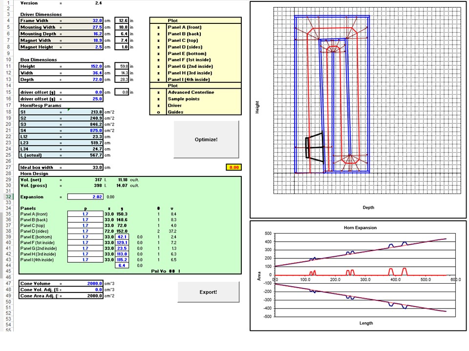
If I recall correctly I read earlier in this thread that a square gives the best mouth termination after a circle. Therefore I altered S4 until I arrived at an ideal box width that matched my actual enclosure width of 33cm. May I assume I have used correct procedure and thinking in arriving at this?
I have to say I get a little thrill watching the Optimise routine reshape the box diagram. This is an extremely clever tool you've constructed Brian.
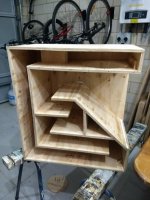
My local hardware sells a range of ply, like all but one country (😉) we adopted metric in the '60's so I work solely in millimetres. Locally I can get 12, 15, 17,18, 19, 21, 23 and 25mm ply. I settled on 17mm as above this size the price rises quickly.
12mm for this THAM10HTL I'm building seems solid. Hoping 17mm will be solid enough for this larger enclosure with some well placed braces?
Next stop Hornresp.
Thanks again.
Thank you Brian!
Seems obvious that the box dimensions would be external!
I think the mix up might be that the Boxplan-MTH uses "Width" in the Box Dimensions section and "Ideal box width" below that - then when you look at the "Panels" section the panel dimensions are then indeed internal sizes. On reflection I think I have arrived at the conclusion I was looking at an internal dimension throughout the worksheet. If I had bothered to look through the panel cell formulas then it would have been immediately obvious the "Box Dimensions" are indeed external! 🙄
Perhaps I might humbly suggest it might help to call out the Box Dimensions heading as "External Box Dimensions" and Ideal box width as "Ideal internal box width"? 😀
This is what i have now....
If I recall correctly I read earlier in this thread that a square gives the best mouth termination after a circle. Therefore I altered S4 until I arrived at an ideal box width that matched my actual enclosure width of 33cm. May I assume I have used correct procedure and thinking in arriving at this?
I have to say I get a little thrill watching the Optimise routine reshape the box diagram. This is an extremely clever tool you've constructed Brian.
My local hardware sells a range of ply, like all but one country (😉) we adopted metric in the '60's so I work solely in millimetres. Locally I can get 12, 15, 17,18, 19, 21, 23 and 25mm ply. I settled on 17mm as above this size the price rises quickly.
12mm for this THAM10HTL I'm building seems solid. Hoping 17mm will be solid enough for this larger enclosure with some well placed braces?
Next stop Hornresp.
Thanks again.
Attachments
Last edited:
Perhaps I might humbly suggest it might help to call out the Box Dimensions heading as "External Box Dimensions" and Ideal box width as "Ideal internal box width"? 😀
Good point. Or just have the ideal box width calculated as the external ideal box width, rather than the internal one. I'll include that in the next update.
If I recall correctly I read earlier in this thread that a square gives the best mouth termination after a circle. Therefore I altered S4 until I arrived at an ideal box width that matched my actual enclosure width of 33cm. May I assume I have used correct procedure and thinking in arriving at this?
That will work, but bear in mind that the response of the TH will also depend on the value for S4. You might have to compromise a bit.
Hi Brian,
Is there a way to turn on dimensions in the box diagram? I am keen to know where the interior boards should be located with respect to the outer boards.Apologies if this is answered in your instructions and I've failed to absorb this information!
Thanks.
Is there a way to turn on dimensions in the box diagram? I am keen to know where the interior boards should be located with respect to the outer boards.Apologies if this is answered in your instructions and I've failed to absorb this information!
Thanks.
Select the "Guides" option. It will show you where to draw guidelines to locate the positions of the internal panels.
Finding board locations
Ok thanks Brian, that did the trick!
It didn't immediately answer my question however, but I did a little more tweaking of the workbook and thought I'd add these here for anyone that might struggle with Excel. Please let me know if I got any of this wrong. The steps I took went a little like this....
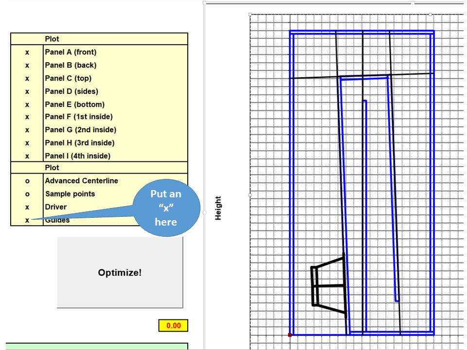
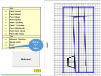
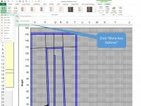
1) So first thing I did was add the "X" next to Guides and the nice black guide lines appear. I also deselected some other options with a letter "o" for clarity....
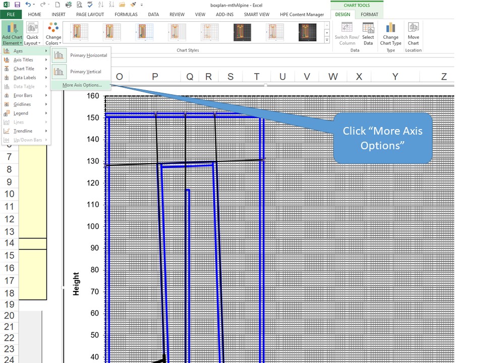
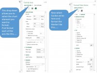
2) Then I added in labels for both the X and Y axis and some Guide marker end points. In the menu along the top of this image you need to be in the "Chart Tools - Design" ribbon. Click on each axis to switch on axis labels. Then click "More Axis Options" to go a little deeper. The menu path I used looks like this...
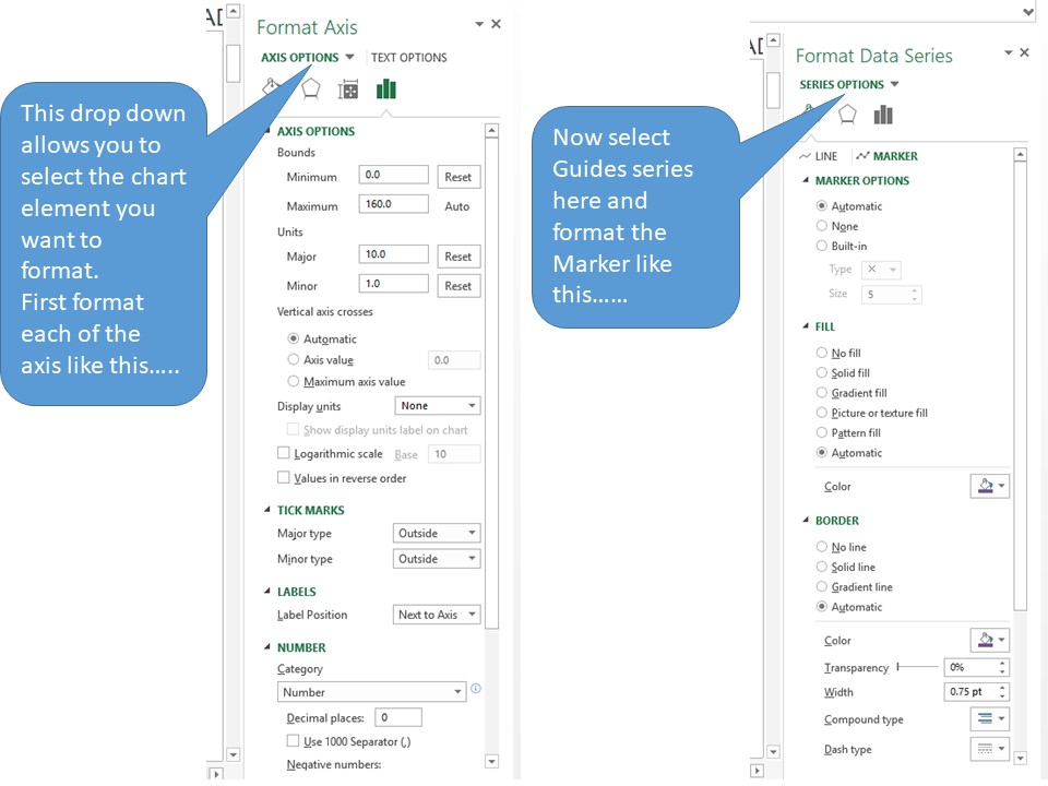
3) Then adjust your "Horizontal (Value) axis" and "Vertical (Value) axis" options so they look like the left image. Then select the Series "Guides" option and adjust to the image on the right.....
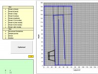
Then the layout chart looks like this....
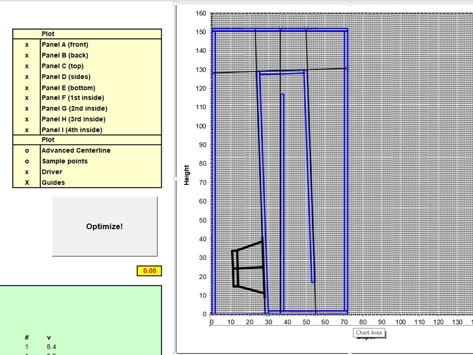
4) Its a bit messy and cluttered like this so then I zoom right in to maximum (I'm really old ).
).
5) Next I hover my pointer over the end of the Guide and I get a little box pop up with the X & Y coordinates. Here I can now see clearly the intersection of the edge of the woofers internal motor board should be 28.2cm from the outside left hand edge of the enclosure. For some reason my pointer did not get captured in the screenshot so I've added in the arrow for clarity...
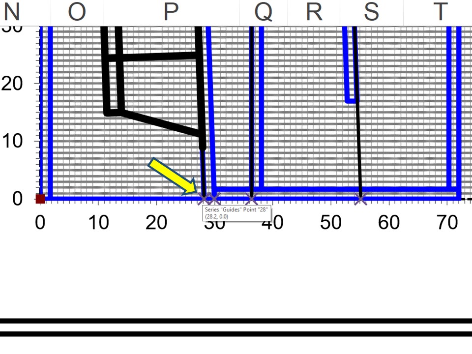
Next I just go around hovering over each of the points where the Guides intersect the outside edge of the enclosure, note the numbers in the popup box and I now know where to place the internal baffles. 😀
Admittedly steps 2), 3) & 4) are not necessary, you can just do 1) & 5) ie. turn on guides and then hover over the end/edge intersection points and read from the popup boxes, but I went this way as it helped me visualise that I was indeed reading off the popup data correctly.
Please let me know if I missed or misrepresented anything here.
Ok thanks Brian, that did the trick!
It didn't immediately answer my question however, but I did a little more tweaking of the workbook and thought I'd add these here for anyone that might struggle with Excel. Please let me know if I got any of this wrong. The steps I took went a little like this....
1) So first thing I did was add the "X" next to Guides and the nice black guide lines appear. I also deselected some other options with a letter "o" for clarity....
2) Then I added in labels for both the X and Y axis and some Guide marker end points. In the menu along the top of this image you need to be in the "Chart Tools - Design" ribbon. Click on each axis to switch on axis labels. Then click "More Axis Options" to go a little deeper. The menu path I used looks like this...
3) Then adjust your "Horizontal (Value) axis" and "Vertical (Value) axis" options so they look like the left image. Then select the Series "Guides" option and adjust to the image on the right.....
Then the layout chart looks like this....
4) Its a bit messy and cluttered like this so then I zoom right in to maximum (I'm really old
). 5) Next I hover my pointer over the end of the Guide and I get a little box pop up with the X & Y coordinates. Here I can now see clearly the intersection of the edge of the woofers internal motor board should be 28.2cm from the outside left hand edge of the enclosure. For some reason my pointer did not get captured in the screenshot so I've added in the arrow for clarity...
Next I just go around hovering over each of the points where the Guides intersect the outside edge of the enclosure, note the numbers in the popup box and I now know where to place the internal baffles. 😀
Admittedly steps 2), 3) & 4) are not necessary, you can just do 1) & 5) ie. turn on guides and then hover over the end/edge intersection points and read from the popup boxes, but I went this way as it helped me visualise that I was indeed reading off the popup data correctly.
Please let me know if I missed or misrepresented anything here.
Attachments

Last edited:
Check the spreadsheet on the "Guides" tab - there's another graph there that adds data points for each guide line.
Export back to Boxplan-mltl?
Hi Brian,
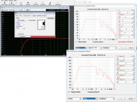
I managed to recreate your nice MLTL sim with a little stuffing.....
But now my next question is how do I get my Hornresp parameters exported out to your Boxplan-mltl?
Again, apologies if I've missed something in your instructions!
Thanks.
Hi Brian,
I managed to recreate your nice MLTL sim with a little stuffing.....
But now my next question is how do I get my Hornresp parameters exported out to your Boxplan-mltl?
Again, apologies if I've missed something in your instructions!
Thanks.
Attachments
But now my next question is how do I get my Hornresp parameters exported out to your Boxplan-mltl?
The process works the other way, LOL.
Seriously, if you're trying to translate that offset TL into a Boxplan-generated design, I suggest doing the following:
1. Enter the driver's EM Parameters in the "Design" spreadsheet - Sd, BL, Cms, Rms, Mmd, Le and Re, Pmax and Xmax
2. Enter the driver's physical dimensions in the "Driver Dimensions" section of the "Design" spreadsheet.
3. Enter the value for S4 in the "Hornresp Params" section of the "Design" spreadsheet
4. Under the "Box Dimensions" section, enter a value for the Width that will leave enough space on the baffle to mount the driver.
5. Keeping an eye on the net box volume in the "Box Design" section, enter values for Depth and Height for the box until the calculated net volume of the box is the net volume from the Hornresp sim plus about 10~20%.
6. Select "Optimize!" and then compare the results against your target sim.
Adjust the Box dimensions and repeat the Optimization routine until you get as close to the target sim as possible.
MLTL - Mastered, well mostly
All good, thanks AGAIN Brian! 🙂
I promise I did read your instructions at the bottom of your Horn Folding page, oh about 25 times! 😉
I guess I had it in my head that once I'd set up, optimised and exported from Boxplan to Hornresp that there would be a return path to export from Hornresp and import back into Boxplan, if that makes sense? 🙄
Anyhow I got it to work, but along the way I broke the MLTL in two different ways:
Anyway I think I came out with a nice initial design and it was quick! Once I had the Boxplan loaded up, the optimise, export, refresh (F6) in Hornresp process is a breeze!
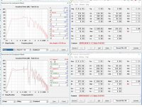
This is what I came up with...
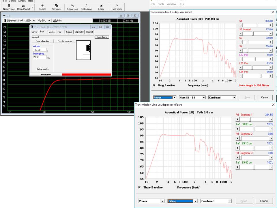
So my take away her is that compared to the same size (110 litre) bass reflex enclosure (left hand WINISD image) the MLTL gets 6db louder for 1 watt input! Am I correct here?
To get this I added 344.5 mks rayls/m resistivity of filling. How much filling of typical pillow polly would this look like please Brian? This is important because the MLTL design modeled response relies on this filling to look this good.
Thanks again!
All good, thanks AGAIN Brian! 🙂
I promise I did read your instructions at the bottom of your Horn Folding page, oh about 25 times! 😉
I guess I had it in my head that once I'd set up, optimised and exported from Boxplan to Hornresp that there would be a return path to export from Hornresp and import back into Boxplan, if that makes sense? 🙄
Anyhow I got it to work, but along the way I broke the MLTL in two different ways:
- I tried making the depth of my enclosure 100cm to see the effect of a long path. When I scaled the box back down to 75cm the optimise routine couldn't refit the first segment back into the box. I tried all manner of changes but had to revert to a previous save.
- Twice I lost the optimise and export buttons. Not sure how, no amount of undo's would bring them back. Again a revert to a previous save was in order.
Anyway I think I came out with a nice initial design and it was quick! Once I had the Boxplan loaded up, the optimise, export, refresh (F6) in Hornresp process is a breeze!
This is what I came up with...
So my take away her is that compared to the same size (110 litre) bass reflex enclosure (left hand WINISD image) the MLTL gets 6db louder for 1 watt input! Am I correct here?
To get this I added 344.5 mks rayls/m resistivity of filling. How much filling of typical pillow polly would this look like please Brian? This is important because the MLTL design modeled response relies on this filling to look this good.
Thanks again!
Attachments
I tried making the depth of my enclosure 100cm to see the effect of a long path. When I scaled the box back down to 75cm the optimise routine couldn't refit the first segment back into the box.
The goal-seeking process in Excel is pretty basic. Some day I'll figure out how to include boundary conditions in the goal-seeking process (e.g. CSA at any point should not go negative). Until then you'll need to use the graph of the enclosure as a guide, e.g. if the graph shows an internal panel that extends out of the box or crosses another panel, manually correct the length of the panel in the spreadsheet before selecting the Optimize option.
Twice I lost the optimise and export buttons. Not sure how, no amount of undo's would bring them back. Again a revert to a previous save was in order.
That's new. I haven't come across that issue during testing.
So my take away her is that compared to the same size (110 litre) bass reflex enclosure (left hand WINISD image) the MLTL gets 6db louder for 1 watt input! Am I correct here?
That can't be right. Passband sensitivity should be similar. Note that Hornresp graphs SENSITIVITY (2.83V/1M), not EFFICIENCY (1W/1M). This is important to remember when comparing with other programs, particularly when low-impedance drivers are being used in the sim.
To get this I added 344.5 mks rayls/m resistivity of filling. How much filling of typical pillow polly would this look like please Brian? This is important because the MLTL design modeled response relies on this filling to look this good.
You're over-thinking it 🙂. Just take note of the target Fb, then stuff until the target Fb is achieved. Measure with DATS or something similar. Look for where the phase changes (crosses zero). Or where the impedance is at a minimum - that should be at or fairly close to Fb.
- Home
- Loudspeakers
- Subwoofers
- Spreadsheet for Folded Horn Layouts...