i deleted it and downloaded the new version
same thing im going to try my desktop pc and see
ill met you know asap
Sigh - I updated the wrong BOXPL workbook.
I just updated the right one (TL2?) this time.
Brian, Is there somewhere that I can find an explanation of the methodology you are using to segment folded horns and determine the HR parameters to represent them?
I used the Advanced Centerline method to determine the centerline of the path, and then for the straight sections of the path I calculate the cross-section at various sample points that are orthogonal to the calculated centerline. For the bends, I just look at the path length and not the volume around the bend. Once there's pretty good correlation between net volume of the resulting sim, and the net volume of the box calculated from its gross volume minus the volume of its panels, I consider the sim close enough for good use.
Brian,
Thanks. But perhaps my real (first) question "what exactly is the Advanced Centerline method ?". I've seen some sketches of right angle bends, but they don't explain the construction lines used. And for bends different from 90 degrees it's obviously even less clear.
I was hoping you wouldn't need to write out a big explanation but rather that such an explanation already exists that you or others could just point me to.
Eric
Sigh - I updated the wrong BOXPL workbook.
I just updated the right one (TL2?) this time.
haha dont start off 2021 that way! we need you

so i tried them all to make sure its not my computer or ignorance because that's usually the problem with me and things that don't work...either that or i didn't read the directions
these ones all give the same error after enabling macros
tl1
tl2
tham
mth
mthalt
vbslot
othorn
wbin
cyclops
roar
6bps
bp6p
cubo
poc7
all the rest seem to work fine
Brian,
Thanks. But perhaps my real (first) question "what exactly is the Advanced Centerline method ?".
Horn Folding - a brief study of the centerline vs advanced centerline method | AVS Forum
Basically at a fold, you draw a line that's orthogonal to the centerline from the focus of the fold to the other side. The the next sample point is located halfway between that pint and the farthest point of the bend.
If im being a pest, than tell me and i wont be offended. I keep buggering up
Your thread and apologize regardless.
But dump the idea of flare and use segments as if they are predictable filters and split the 180 by the median between the two seperate CSA (an increase)segments. shoot it full Length for all folds as such. giving half to each and making this steps within reason to support the 1/3,2/3 rule of both harmonics and ‘flow’ in a manifold. . . an elipse is not a circle, and its the pattern of a spread in flow of particles as mass in a gas around a turn will show. theres a lot of things to ponder, but if the nulls are not in the turns, then flow through them is. if the idea is to create the best possible phase between the front and rear then the middle of that is going to suffer as well as the ends. Until We decide to create a double tapped split and fold, its offsets to buy back and cheat with.
The isobaric might seem funny, but it stirs up attention. even if its not preferred. its the rest that is important here. This split and fold is merely missing a csa to use in each segment and a driver to make happy. thatll never change, but what is phase at the exit of this two stage pipe if we want it to be something? Even hypothetically?
At some point we must ask ourselves if we are trying to make a nice box that's comvenient, or can we give into reality of sound a let that slip a bit to see? its really probably not as bad as we think. We just need to get over that hurdle to then shrink it back from there once we find what apparently we wont look at.
Attachments
Last edited:
Hi Brian,
what if I add another fold in BP6S ? Love the easier built!
That will drive Fb down quite a bit further. Might be useful if you're trying to get Fb down below 40 Hz.
Basically at a fold, you draw a line that's orthogonal to the centerline from the focus of the fold to the other side. The the next sample point is located halfway between that pint and the farthest point of the bend.
Brian,
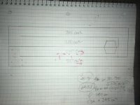
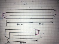
Thanks, but sadly I'm still not quite getting it. Maybe this example helps. The drawings attached show an arbitrary enclosure with a fold. The first drawing shows the internal box dimensions (in cm), with the closed end at the bottom, open end on the right, and the driver center at a point 20 cm above the bottom panel.
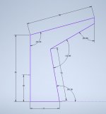
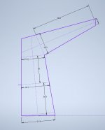
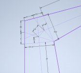
The second drawing shows my attempt (still incomplete) to derive the HR inputs by applying the advanced centerline method.
Assuming the enclosure is 10 cm wide, I get:
S1=219
S2=183
S3=151
S4=143
S5=40
L12=20.9
L23=18.0
L34=?
L45=38.9
Is this the correct application (so far) of the ACM?
If "No", what's wrong?
If "Yes", then how do I draw the additional construction lines to determine L34? Do they just go from the inner corner of the bend to the spot where the centerlines intersect the walls? Or do I trisect the angle between the two lines from which S3 and S4 are derived? Or some other method?
Thanks,
Eric
Attachments
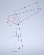
You're most of the way there already.
I've updated your second diagram to show how I define the path around the bend using the Advanced Centerline method. Note that this method should not be used to determine the VOLUME changes through the bend, only the best estimate of the path length through the bend. Volume estimates should only be based on sample lines that are orthogonal to the center line. The Advanced Centerline method assumes that the expansion uniformly increases or decreases through the bend.
I've updated your second diagram to show how I define the path around the bend using the Advanced Centerline method. Note that this method should not be used to determine the VOLUME changes through the bend, only the best estimate of the path length through the bend. Volume estimates should only be based on sample lines that are orthogonal to the center line. The Advanced Centerline method assumes that the expansion uniformly increases or decreases through the bend.
Attachments
180 degrees twice is zero. These are self canceling attributes on many many levels. Including the need for Centerline as it isnt in question as it might be otherwise? Except they also create even ‘tiers of 3’. a folded path and at the first harmonic interval in succession. A CSA change if needed, and a way to tune between sims nulls instead of find them in the RTA as erroneous. Flares and tapered chunks and transients of real music?? When a standing wave actually does get burped out to hear, not just assumed its part of an XO or even could be. i dont know yet that a dsp is better but im trying.. long long road to explain what sounds emit out if these designs like. But take it from whoever will comment in experience(not only a sim) , theres clearly more to hear if you can. Its not all good, theres bad.
Last edited:
Brian, can you provide some guidance on how to choose a certain folding pattern, at a high level?
For example, I know what shape I would like my speaker to be and the dimensions, and a potential driver. Going from that information to a folding pattern is where I get a bit lost.
My current subwoofer is the Exodus Anarchy tapped horn and am pleased with its performance and integration. I would like to refold to fit under an existing corner horn, keeping the height to a minimum. The shape of the corner horn is a pentagon. Looking for some guidance on how to approach this.
Two folds in 3 segments. But once crossing another path or parallel to one that is halved . The top sketch if ‘tapped’ might need to be folded in half again ‘after the tap? I cant see how this is wrong, and ive tried to mass load the end to see if a tapped horn with a huge mouth deviates. IT DOES! And it goes like a super MLTL, but with a horny gain?
Attachments
Brian, can you provide some guidance on how to choose a certain folding pattern, at a high level?
Follow the KISS principle. The simpler the build, the less mistakes you're likely to make, and the less disappointment you'll have with the result
.Follow the KISS principle. The simpler the build, the less mistakes you're likely to make, and the less disappointment you'll have with the result
Thank you. Ok, after looking at the various shapes you have, this looks simplest - given the end shape.

Last edited:
Garbled geometry from POC7 and Microwrecker
Hello Brian,
Both POC7 and Microwrecker designs are quite attractive for their ability to fit a long line within a given volume but whenever I input my preferred dimension, 120*100*75 cm in the sheets and click "optimize"button, I end up with a garbled mess of lines, horn tapering down in CSA and even driver reversal. This doesn't happen with other sheets I have used.
Is there a rule of thumb or an algorithm to be followed with these sheets?
Change the dimensions in smaller steps
The regression analysis in those workbooks isn't perfect, and trying to change any dimension in a dramatic fashion could lead to what you experienced. To avoid that from happening, change the dimensions in smaller steps, e.g. 50->60->70->80 rather than 50->80.
The regression analysis in those workbooks isn't perfect, and trying to change any dimension in a dramatic fashion could lead to what you experienced. To avoid that from happening, change the dimensions in smaller steps, e.g. 50->60->70->80 rather than 50->80.
- Home
- Loudspeakers
- Subwoofers
- Spreadsheet for Folded Horn Layouts...