AWESOME upgrades David!
They had better be, considering the amount of work required to implement them
") .
.Are cylindrical segments the same as conical?
Please don't ditch parabolic
Hi Dan,
The Con, Exp and Par options in the Loudspeaker Wizard will not change. It's just that when the wizard is used with the stepped segments option selected, all the segments will be cylindrical no matter what profile is specified. This limitation will only apply to the stepped segments option, and is required to avoid having to increase the number of area sliders in the wizard.
All this assumes that I will be able to get the thing to work, which will not be a trivial task - at this stage it is no more than a series of ideas
.Kind regards,
David
Does anyone know why xmax goes up a few mm if you enable LE, without changing any other setting?
More information required.
What do you mean by "enable LE"?
By "xmax" are you referring to the maximum displacement seen on the diaphragm displacement chart?
(The value of the 'Xmax' parameter is specified by the driver manufacturer - that will not change).
An example showing the effect you refer to would be helpful.
Hi David,
Thank you for the constant effort putting into improving Hornresp
It's a really useful and accurate software giving results really close to measurements, sometimes even closer to reality than more complicated software like ABEC.
Just a little question, would it be possible to include a way to take into account port and chamber losses? Because I find that sometimes the output level from the port is a bit overestimated. I managed to do it by putting some filling materials in the rear chamber or increasing the acoustic path length between outputs but when having a front loaded horn with a rear vented chamber it's not possible to put filling.
Warmest greetings,
Florent
More information required.
What do you mean by "enable LE"?
By "xmax" are you referring to the maximum displacement seen on the diaphragm displacement chart?
(The value of the 'Xmax' parameter is specified by the driver manufacturer - that will not change).
An example showing the effect you refer to would be helpful.
It might be the Lossy LE in the wizard, it appears the default on state of Lossy Le is retained by the Baseline no matter what, it also takes some flipping of "switches" to turn off Lossy LE but ultimately the radio button is checked when the Lossy LE is off.
It's 180 degrees out of phase

but when having a front loaded horn with a rear vented chamber it's not possible to put filling.
Hi Florent,
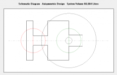
Model the front loaded horn with rear vented chamber as a compound horn. Filling material can then be added to the chamber (segment 1) and/or port tube (segment 3) as shown in the attachment. The horn itself will be limited to a single Con, Exp or Par flare.
Kind regards,
David
Attachments

If it's in the HELP files I missed it.
Attachments
It might be the Lossy LE in the wizard, it appears the default on state of Lossy Le is retained by the Baseline no matter what, it also takes some flipping of "switches" to turn off Lossy LE but ultimately the radio button is checked when the Lossy LE is off.
It's 180 degrees out of phase
Hi Dan,
If the lossy inductance option has been specified on the input parameters window (ie. Le label is red), then when the Loudspeaker Wizard is opened the 'Lossy Le' checkbox is shown ticked and the results take lossy inductance into account.
The Loudspeaker Wizard initial baseline does not take lossy inductance into account even if the option has been selected on the input parameters window. This may be changed in the next update.
Removing the Loudspeaker Wizard 'Lossy Le' checkbox tick calculates results without taking lossy inductance into account. The initial baseline is not affected either way by the 'Lossy Le' checkbox status.
I don't follow what you mean by "It's 180 degrees out of phase". More information would be appreciated.
Kind regards,
David
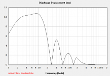
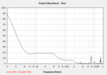
I know enabling Le is for better measure high BL drivers but i did not expect Le would have such high impact on the xmax. I also wonder what frequencies the Le is applied too is this full scale or just one or two ranges.
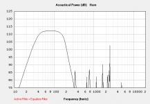
Here is an example of high xmax Le off/on on the POC4 2.83v 8 Ohm:

Here is an example of high xmax Le off/on on the POC4 2.83v 8 Ohm:

+1.Hi David - that stepped allowance is really cool !

David, if you manage it, do you think stuffing feature should be working in this case ?[...]
Incidentally, once I clear all the bugs, I want to get back to further investigating the possibility of modifying the Loudspeaker Wizard to accept stepped cylindrical horn segments only. I think that this should be a lot easier to do than having to also allow for Con, Exp and Par flare stepped segments.
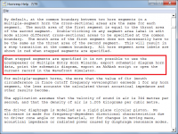
My BP8 simed as stepped segment TH bellow. Vent sizes were decided with BP8 wizard vent velocity screens. Active filtering is just a low pass at 5hz and a -7db eq @6hz, as over-excursion protection. It seems really doable. Filtering of the 53cm long vent spike @350hz seems optimistic beeing so near the mouth.
Attachments
Last edited:
I know enabling Le is for better measure high BL drivers but i did not expect Le would have such high impact on the xmax. I also wonder what frequencies the Le is applied too is this full scale or just one or two ranges.
Here is an example of high xmax Le off/on on the POC4 2.83v 8 Ohm:
View attachment 735602
It affects ALL drivers to some aspect or another. Some are much worse than others. It also has effects on ALL aspects of performance over the entire frequency range of operation. Driver excursion included.
I know enabling Le is for better measure high BL drivers but i did not expect Le would have such high impact on the xmax.
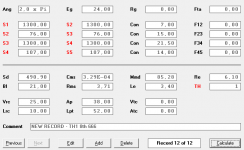
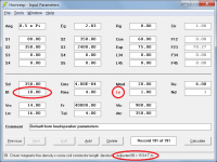
The lossy inductance empirical model was originally developed by 'just a guy' using driver performance data provided mainly by Josh. The model reduces the value of Bl used in the Hornresp calculations, based on the specified values of Le and Re. With the Lossy Le option selected, the adjusted Bl value used by the program can be seen in the status bar panel at the bottom of the input parameters window when the mouse pointer is moved over the Bl input box, as shown in the attachment.
Attachments
- Home
- Loudspeakers
- Subwoofers
- Hornresp