Here's a few pics of what I have been up to for the last few months (Pre-amp and Power Amp).
Each unit has it's own Arduino Uno board.These micros are dirt cheap and in my opinion you would be hard pressed to find a cheaper alternative for DIY electronic projects.
A few details:
The pre-amp is based on a TI stereo volume control chip (PGA2320),it utilizes
a 3.2 inch resistive touch display from 4D Systems,this company has provided
a lot of free development tools to facilitate working with their displays.Input source selection uses an Analog Devices SSM2404 analog switch,2 line level sources can be switched in.Both chips are controlled by the Uno board,you can use the touch screen to set the volume or use the knob.
The Pre-amp/Amp also have capacitive touch capability from the front panel,The brass rods connect to a 12 channel capacitive sense controller from Sparkfun(MPR121),I realize this is redundant but I wanted the ability to develop with both methods from one box. I am treating both units as development tools for future projects.
The Sure 250 watt Class D amp has really exceeded my expectations, (aside from the PWM frequency adjustment issue).The Amp runs very cool even at High listening levels.I added a temperature sensor(LM35) to the Amp to monitor the heat sink temperature,this info is displayed on the screen.Since this unit is micro controlled I could easily add code to activate a cooling fan if desired.
I designed both the boxes in the "Arts and Crafts" style,I wanted to achieve a sense of depth from any viewing angle so I offset most of the joinery.
The very rare 3 string acoustic guitars were an afterthought...BTW I used genuine Martin guitar strings!
Here is a link to more photos:
robertcottiers's Album: Arduino Audio Projects
Bob C.
Hello, can you please show some links or schematics on amp control by arduino?
Great job!
Last edited:
Doing the hardware first (2 identical units) and then deciding what to actually stick in them. Still need cleaning up and anodizing. Sinks should be good for up to around 80W per channel class-A
Hi Jasonp4113,
80W rms, pure class A, is at least 3-400W in heat
 .
. Too much for that case, IMMO.
Member
Joined 2004
Hi: I don't have any schematics generated for either unit, I do most of my projects just by using datasheets.....Both of these units are an ongoing project and will have other functionality in place over the next few months.
I will be adding a 3-way active crossover to the pre-amp(Linkwitz/Riley 24 dB/Oct)utilizing Digital Potentiometers to set Crossover points. Direct entry from the touch screen will set the crossover points(saved to EEprom).
At some point I will get everything into Eagle!
Thanks for commenting...
Bob C.
Schematics
Hello,
Any further description of the project?
Thanks in Advance
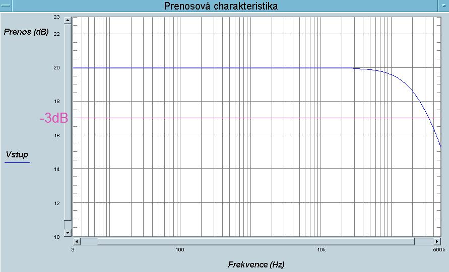
Measured
Hello,
Any further description of the project?
Thanks in Advance
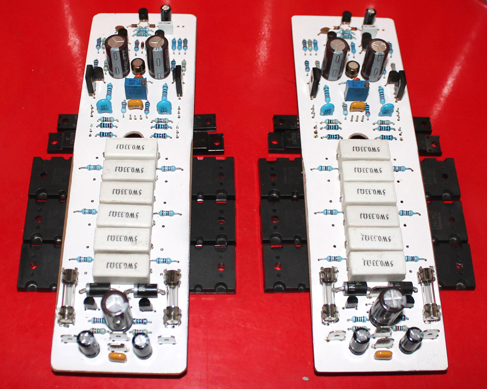
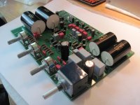
Another Honey Badger is alive. Built with OS's Mouser BOM, I used MPSA-18s for the input pair, MJE15034/5 and NJW0281/0302. Input pair Hfe = 580 left and 579 right, exact match for each pair according to my cheap meter, less than 1mv offset on initial power up. Following the build guide, power up went smoothly, the only nerve wracking part was bringing the bias up. I was surprised how many turns it took to get the bias to start.
I haven't had a chance to do any critical listening yet, so no comment. Eventually want to do a Leach/Honey Badger shoot out. 5 pair Leach biased at 50 mA/device vs. 100 mA/device Honey Badger.
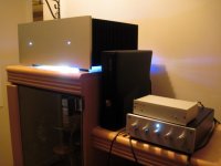
I'm still working up a design to send to Front Panel Express for this and the Leach below it. Source is an Oppo BDP-103 feeding the amps directly. The receiver in the background is doing surround channel amp duty and providing remote control triggering for my home made sequencer. Planning to add a direct remote control for the sequencer using usb power from the BDP-103 to trigger.
I haven't had a chance to do any critical listening yet, so no comment. Eventually want to do a Leach/Honey Badger shoot out. 5 pair Leach biased at 50 mA/device vs. 100 mA/device Honey Badger.
I'm still working up a design to send to Front Panel Express for this and the Leach below it. Source is an Oppo BDP-103 feeding the amps directly. The receiver in the background is doing surround channel amp duty and providing remote control triggering for my home made sequencer. Planning to add a direct remote control for the sequencer using usb power from the BDP-103 to trigger.
Attachments
Last edited:
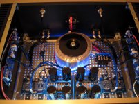
One of my 300B tube amps is flat to 52KHz but the OPTs were $300 each.
What did you use?
My DIY effort
Hi,
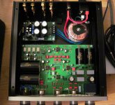
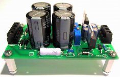
I'm a student in electrical engineering from Quebec, Canada and a few weeks ago, I completed these two projects. The first one is a F-5 from Nelson Pass. That wasn't that difficult given that the building guide on DiyAudio is pretty clear and easy to follow.
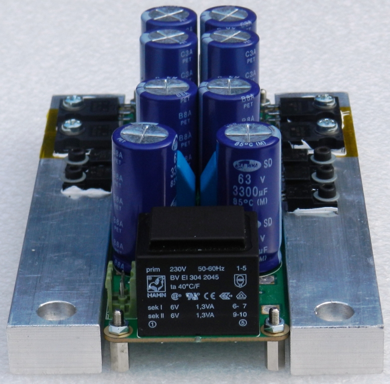
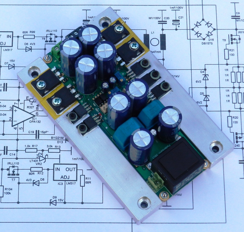
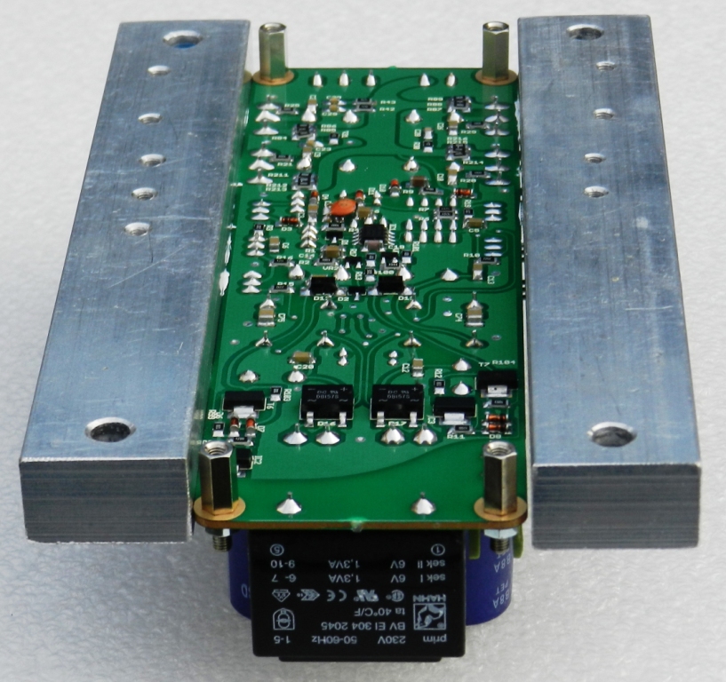
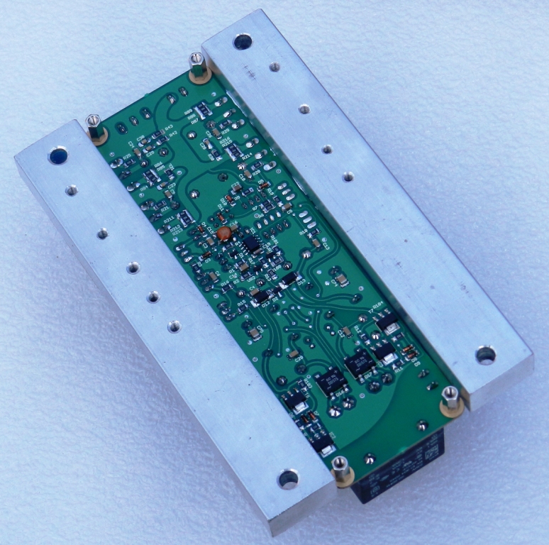
The second project is unique. It is a full function multichannel preamp. It has 4 input. A phono stage with enhanced RIAA curve. There is a Baxandall 3-band EQ for bass, mid range and treble adjustments. One input buffer (ne5532) and one output buffer. The output buffer is basically the B1 buffer by Nelson Pass. The input is selected by a rotary switch that activate relays. I also made the variable PSU that can goes from +/- 1.5 V to 37 V (1.5A). It is a typical circuit with just few changes(it has a very good ripple rejection of around 80 dB)...
The two PCBs has been conceived by me and everything is working fine.
The amplifier sound fantastic!!! =P
Hi,
I'm a student in electrical engineering from Quebec, Canada and a few weeks ago, I completed these two projects. The first one is a F-5 from Nelson Pass. That wasn't that difficult given that the building guide on DiyAudio is pretty clear and easy to follow.
The second project is unique. It is a full function multichannel preamp. It has 4 input. A phono stage with enhanced RIAA curve. There is a Baxandall 3-band EQ for bass, mid range and treble adjustments. One input buffer (ne5532) and one output buffer. The output buffer is basically the B1 buffer by Nelson Pass. The input is selected by a rotary switch that activate relays. I also made the variable PSU that can goes from +/- 1.5 V to 37 V (1.5A). It is a typical circuit with just few changes(it has a very good ripple rejection of around 80 dB)...
The two PCBs has been conceived by me and everything is working fine.
The amplifier sound fantastic!!! =P
Attachments
Member
Joined 2004
Member
Joined 2009
Paid Member
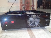
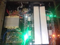
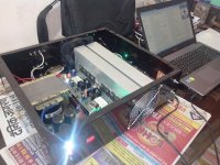
250W+250W integrated amp
Hi,
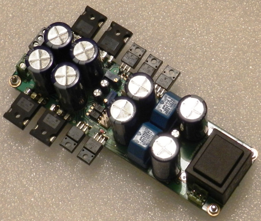
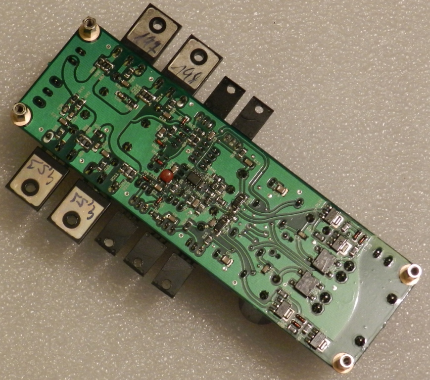
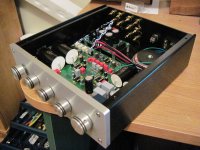
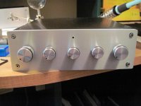
some pics of my new build. a 250+250W @4 ohm integrated amp, the main amp was designed by myself, PCB's designed by AlexMM, a simple soft start designed by me, protection based on Rod Elliott's design and the preamp based on Elliott's P97 preamp. Sounds fantastic. Bass punches in the chest with such an authority over the cone movement. Chassis is made at local sheet metal shop using 1.5mm steel.
Cheers!!!!
Aniket")
Hi,
some pics of my new build. a 250+250W @4 ohm integrated amp, the main amp was designed by myself, PCB's designed by AlexMM, a simple soft start designed by me, protection based on Rod Elliott's design and the preamp based on Elliott's P97 preamp. Sounds fantastic. Bass punches in the chest with such an authority over the cone movement. Chassis is made at local sheet metal shop using 1.5mm steel.
Cheers!!!!
Aniket
Attachments
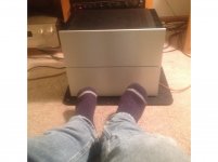
Mighty beast almost finished, silver plated badges still to come.:banana:
An externally hosted image should be here but it was not working when we last tested it.
An externally hosted image should be here but it was not working when we last tested it.
An externally hosted image should be here but it was not working when we last tested it.
An externally hosted image should be here but it was not working when we last tested it.
- Home
- Amplifiers
- Solid State
- Post your Solid State pics here