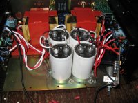
Stabilized power supply 800V for tube amplifier.
Stabilized power supply 800V for tube amplifier.
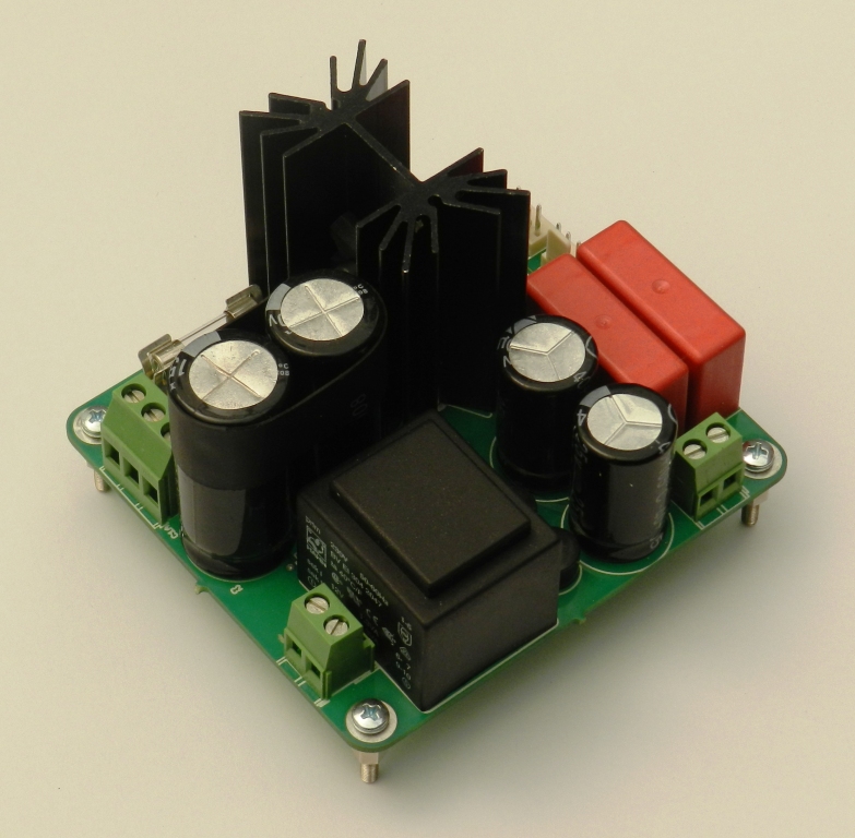
Stabilized power supply 800V for tube amplifier.
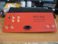
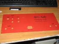
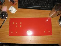
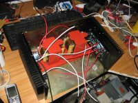
2x120W/4ohm dual monoblock full DC amplifier with integrated PCM2706 DAC.
Attachments
-
 3.jpg277.8 KB · Views: 1,373
 -
 IMG_6538.jpg221.5 KB · Views: 385
 -
 IMG_6537.jpg219.8 KB · Views: 405
 -
 IMG_6490.jpg221.3 KB · Views: 289
 -
 IMG_6487.jpg247.2 KB · Views: 359
 -
 IMG_6461.jpg367.2 KB · Views: 432
 -
 IMG_6447.jpg201.7 KB · Views: 501
 -
 IMG_6445.jpg286.7 KB · Views: 464
 -
 IMG_6438.jpg308.3 KB · Views: 1,278
 -
 IMG_5343.jpg316 KB · Views: 1,332
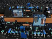
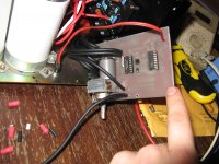
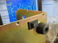
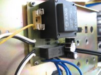
The input selector and "power on" are by one switch, I have modified this schematic - Step Switch Selector
Just connected Q4 to pin 15 (for three inputs) and have used ULN2003 for relay switching instead 4066 + diode logic (summing all three input relays) to fourth relay - this for power transformers. That allows to switch all three inputs and power on by only one push button. It has also mains power off switch.
Regards,
Milen
Attachments
-
 IMG_6657.jpg151.1 KB · Views: 238
 -
 IMG_6654.jpg139.4 KB · Views: 310
 -
 IMG_6558.jpg467.5 KB · Views: 324
 -
 IMG_6555.jpg349.2 KB · Views: 300
 -
 IMG_6553.jpg309.7 KB · Views: 295
 -
 IMG_6552.jpg247.8 KB · Views: 235
 -
 IMG_6551.jpg327 KB · Views: 235
 -
 IMG_6542.jpg142.5 KB · Views: 207
 -
 IMG_6541.jpg206.8 KB · Views: 232
 -
 IMG_6539.jpg379.3 KB · Views: 334
http://www.customworks.cz/amplifiers/hypa170/
An externally hosted image should be here but it was not working when we last tested it.
Last edited:
http://i56.servimg.com/u/f56/17/42/39/81/2012-010.jpg
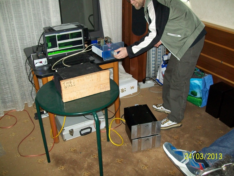
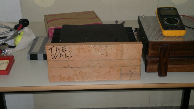
ciao a tutti questo l'o fatto io, un 5w in classe A bjt il frontale sono mattoni veri ed e' dedicato ia mitici pink floid .
CLASS A FIRST
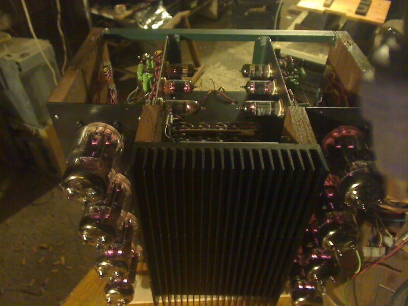
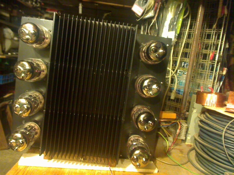
My system repeater 120 watt Class A - three bands perfect solution AKVABLOK ??????????? ???????????? ??????????? - YouTube and even roller ??????????? ???????????? ???????????. ?????2 - YouTube
My system repeater 120 watt Class A - three bands perfect solution AKVABLOK ??????????? ???????????? ??????????? - YouTube and even roller ??????????? ???????????? ???????????. ?????2 - YouTube

ideafolle... please read your private message. English only please 🙂
(ideafolle... si prega di leggere il tuo messaggio privato. Italiano solo per favour)
My system repeater 120 watt Class A - three bands perfect solution AKVABLOK ??????????? ???????????? ??????????? - YouTube and even roller ??????????? ???????????? ???????????. ?????2 - YouTube
oh my God sir I just saw the video incredibly big class A, I like the wood chassis design looks elegant 😀 the power supply is about 90V DC ?
Best Regards
Juan
Sir Juan, supply voltage + and - 43 volts stably and served on akkamulyatorny buffer at the entrance to the stabilizer 60 volts. Storage capacitors 5 pieces 10000 x 100V. And stabilizer circuit can lay out.oh my God sir I just saw the video incredibly big class A, I like the wood chassis design looks elegant 😀 the power supply is about 90V DC ?
Best Regards
Juan
Figured I should introduce myself in a build thread 😉
I'm new to the diyaudio forum but this is my 4th amplifier build, I started building DIY amps+speakers about 20 years ago in high school and did a degree in EEE. What I'm about to post here is my current build but the technology will seem a little old because I bought all the parts in about 2003 while I was doing a (non-EEE) PhD. I decided that finishing the PhD was more important than louder music so I put it all in a cupboard where it stayed while I got married, had kids, etc: life happened. I recently decided to just do the damn build already.
What it is is a 6.1 home theatre system that will get used for music more often than movies. 7-channel HT was invented AFTER I designed all this, so once the 6 channels are all built, I'll think about the 7th.
Each of the 6 channels is 3-way actively crossed over, with 100+50+50W RMS per channel. Stereo pairs (2x100+4x50) live in 3U rack cases, and I'm nearly done assembling the first.
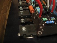
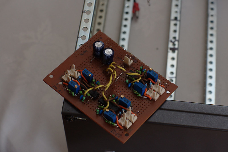
The 100W channels are Si Chip "Ultra Low Distortion" BJT amps, a design that has been updated twice since I bought these kits. Here's one channel hanging off the 80mm fan-tunnel heatsink:
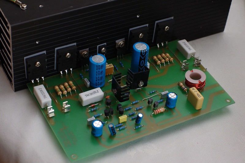
(the safety resistors are still in, I plan to bias them tomorrow)
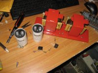
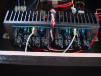
Here's the ironmongery, a 35+35 300VA and 12+12 20VA to run the two 100W channels, plus a 25+25 300VA to run the four 50W channels:
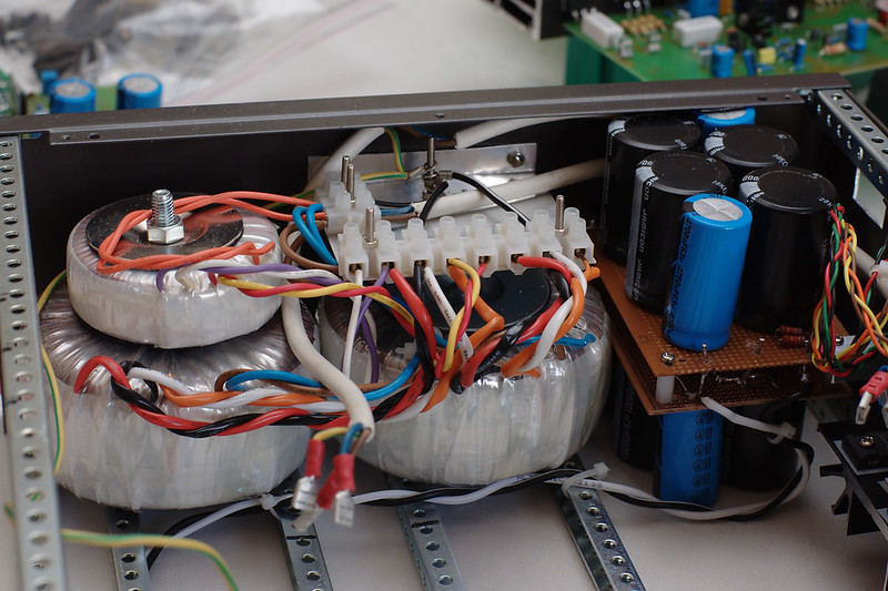
The two windings of the 12+12 are put on the outermost edges of the 35+35 to give 47+47 which is linear-regulated down to 55+55 DC for the IPS+VAS. Don't worry, I won't forget the nut on the ground star 😉 Filter caps are 4x10,000+2x4700uF per rail, so a total of about 0.1F/70V for both rails of both channels.
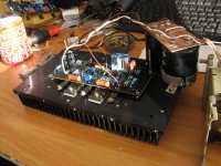
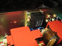
Here's an overview of the power control stuff, bolted to the inside of the front false panel:
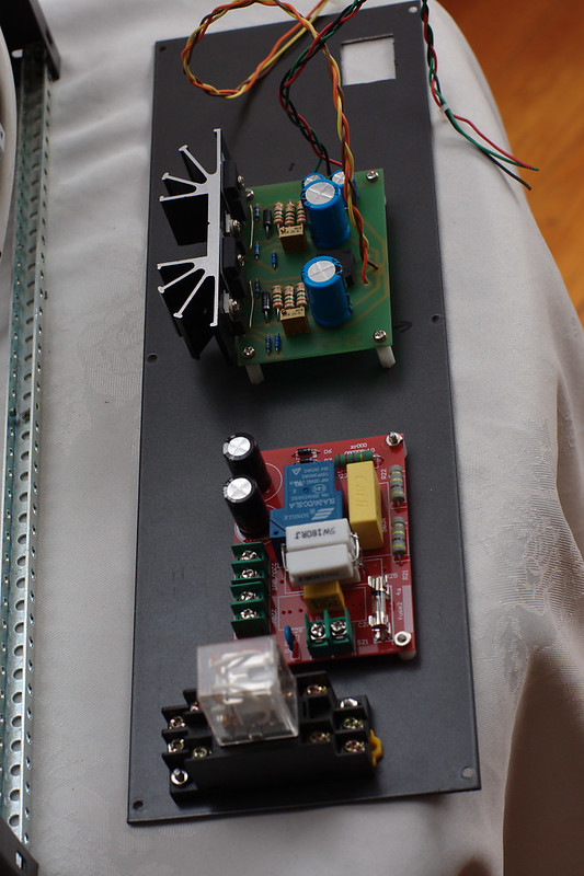
Top to bottom, you can see the linear regulator board for the 2x100W, the soft-start board and a power relay for switching the mains (remote control signal from HT receiver and thermal cutout via microcontroller). The soft start is a cheap chinese kit that I replaced its crappy little resistor with 4x180R 5W wirewounds as you can see.
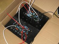
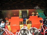
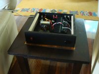
Here's an overview of the case with all the PSU stuff installed and tested:
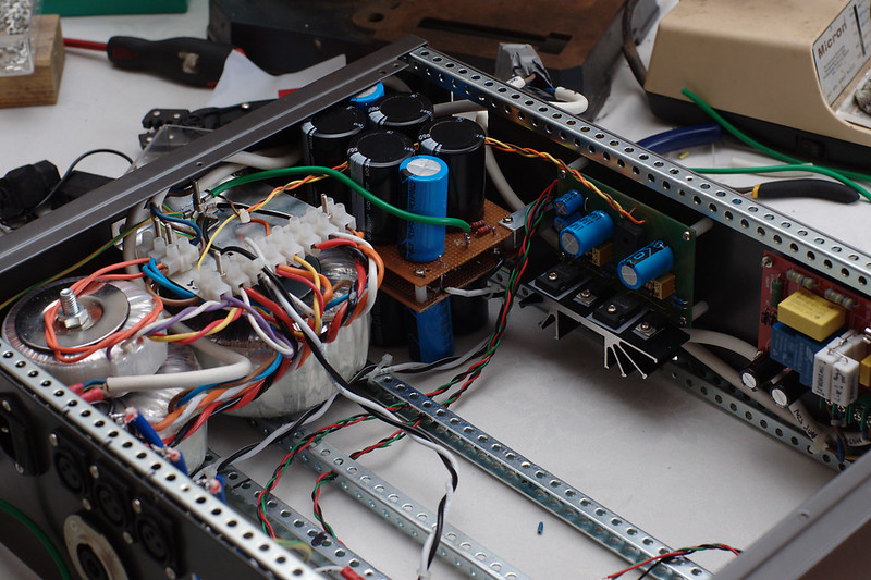
You can see on the back panel that it has 6*XLR inputs and 2*Neutrik 8-pole outputs (no accidental band confusion between amp and speaker!). The XLRs are because I'm using DCX2496s as crossovers; I actually built a whole pile of op-amp LR4 crossover boards but it was such a HUGE chore wiring them up, with no flexibility or ability to time-align through digital delays etc, that I've given up on that route. I may be selling a few TL074 LR4 PCBs later if people want them...
And because it's balanced, here are the 6 differential inputs:
They're the variable-gain arrangement of Figure 11 in Doug Self's page about balanced IO, built using half a TL074 per channel. Powered from 15+15V. It mounts on top of the heatsink tunnel, right under the top of the case.
Not pictured here are the four LM3886 chip amps that do the mid+high channels. Not very interesting, but they'll appear in a photo later once I get everything in the rack case. It is absolutely chock full.
Total build time on this box so far: about 3 weeks elapsed, doing an hour or two of work most nights. With any luck, I will hear it tomorrow, though the thermal controller isn't done yet - waiting on Arduino Nanos and super-quiet PWM fans to arrive in the post. Most of the code for that is written though.
The loads attached to this are Vifa speakers in home made cabinets, infinite baffle (39Hz F3 Q=0.6 IIRC), nothing fancy. M26WO-06-08, M10MD-39-08, D27TG-35-06. There are Shivas for subs too (non-DIY amp; Behringer EP2500), but not assembled yet because we haven't had the "yes there will be more furniture and where will you put it" discussion yet 😉
I'm new to the diyaudio forum but this is my 4th amplifier build, I started building DIY amps+speakers about 20 years ago in high school and did a degree in EEE. What I'm about to post here is my current build but the technology will seem a little old because I bought all the parts in about 2003 while I was doing a (non-EEE) PhD. I decided that finishing the PhD was more important than louder music so I put it all in a cupboard where it stayed while I got married, had kids, etc: life happened. I recently decided to just do the damn build already.
What it is is a 6.1 home theatre system that will get used for music more often than movies. 7-channel HT was invented AFTER I designed all this, so once the 6 channels are all built, I'll think about the 7th.
Each of the 6 channels is 3-way actively crossed over, with 100+50+50W RMS per channel. Stereo pairs (2x100+4x50) live in 3U rack cases, and I'm nearly done assembling the first.
The 100W channels are Si Chip "Ultra Low Distortion" BJT amps, a design that has been updated twice since I bought these kits. Here's one channel hanging off the 80mm fan-tunnel heatsink:
(the safety resistors are still in, I plan to bias them tomorrow)
Here's the ironmongery, a 35+35 300VA and 12+12 20VA to run the two 100W channels, plus a 25+25 300VA to run the four 50W channels:
The two windings of the 12+12 are put on the outermost edges of the 35+35 to give 47+47 which is linear-regulated down to 55+55 DC for the IPS+VAS. Don't worry, I won't forget the nut on the ground star 😉 Filter caps are 4x10,000+2x4700uF per rail, so a total of about 0.1F/70V for both rails of both channels.
Here's an overview of the power control stuff, bolted to the inside of the front false panel:
Top to bottom, you can see the linear regulator board for the 2x100W, the soft-start board and a power relay for switching the mains (remote control signal from HT receiver and thermal cutout via microcontroller). The soft start is a cheap chinese kit that I replaced its crappy little resistor with 4x180R 5W wirewounds as you can see.
Here's an overview of the case with all the PSU stuff installed and tested:
You can see on the back panel that it has 6*XLR inputs and 2*Neutrik 8-pole outputs (no accidental band confusion between amp and speaker!). The XLRs are because I'm using DCX2496s as crossovers; I actually built a whole pile of op-amp LR4 crossover boards but it was such a HUGE chore wiring them up, with no flexibility or ability to time-align through digital delays etc, that I've given up on that route. I may be selling a few TL074 LR4 PCBs later if people want them...
And because it's balanced, here are the 6 differential inputs:
They're the variable-gain arrangement of Figure 11 in Doug Self's page about balanced IO, built using half a TL074 per channel. Powered from 15+15V. It mounts on top of the heatsink tunnel, right under the top of the case.
Not pictured here are the four LM3886 chip amps that do the mid+high channels. Not very interesting, but they'll appear in a photo later once I get everything in the rack case. It is absolutely chock full.
Total build time on this box so far: about 3 weeks elapsed, doing an hour or two of work most nights. With any luck, I will hear it tomorrow, though the thermal controller isn't done yet - waiting on Arduino Nanos and super-quiet PWM fans to arrive in the post. Most of the code for that is written though.
The loads attached to this are Vifa speakers in home made cabinets, infinite baffle (39Hz F3 Q=0.6 IIRC), nothing fancy. M26WO-06-08, M10MD-39-08, D27TG-35-06. There are Shivas for subs too (non-DIY amp; Behringer EP2500), but not assembled yet because we haven't had the "yes there will be more furniture and where will you put it" discussion yet 😉
Last edited:
Attachments
TGM8
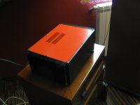
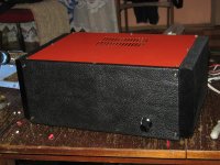
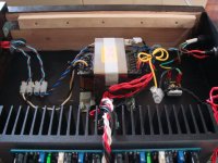
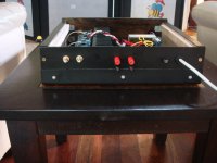
Presenting Bigun's TGM8 design in a stereo amplifier. Details here: http://www.diyaudio.com/forums/solid-state/245619-tgm8-amplifier-based-rod-elliot-p3a.html
This is my first attempt at a case built from scratch using sheet steel for the chassis and backplate, and stained Tasmanian Oak for the other panels.
Attachments

laplace that's really neat
Cheers. Got it biased today and it played its first album through old speakers with passive xovers connected to the LF amps.
Just need to finish assembling the case front, reattach the LM3886s and it'll be done except for the fan control.
- Home
- Amplifiers
- Solid State
- Post your Solid State pics here