Edmond Stuart said:
Hi Brian,
Sure, deja vu. This fruitless discussion is lasting for a year now.
Isn't it unbelievable how stubborn some people can be.
Maybe the holy grail of error correction is a vital element of their religion.
Cheers, Edmond.
Edmond, let me repeat something that I've stated over and over, clearly while the two implementations may have similar distortion reduction behavior, the implementations are different. This is what several of us have been pointing out to you and others, I tried by pointing out the null control. I'm not saying that I favor a null control, just pointing out that it is an implementation difference.
Now, I'm sure that you're familiar with sensitivity analysis, that is where we consider each component and how deviations from the nominal value impact the amplifier transfer function. Certainly, the components in the two designs will have different sensitivities with regard to how they impact distortion, stability and many more system parameters. I'm not going to say which is better since I've not done or seen the analysis, just that they are different. It is a complex problem and I don't think people should be so dismissive of HEC it lead to your new design after all.
I was aware of the old Tiger designs, and the Brystons which have high local output stage feedback, so yours was not the first implementation. However, yours is different and, based on simulation seems to provide excellent performance so while many here claimed the analogy was obvious (sure for anyone who read the literature, yes I did by the way) there does not seem to be an implementation such as yours in the public domain, to the best of my knowledge. So, it seems that it was not so obvious except in peoples heads. I am pleased that my challenge resulted in your new output stage design.
I am aware that all the pieces in your design have been done before, as some here have pointed out, but your complete design has not as far as I know. I welcome references to existing power amp output stage schematics that use your topology for those who claim it has been done.
Pete B.
Re: Re: Re: Re: Re: Re: Re: hec != hoax ?
Again, it seems that it should be easy to provide some gain in this HEC output stage where you've gone to CFP drivers which as I've pointed out before should eliminate the need for boosted front end supply. I like to see the two converging as far as complexity goes.
Pete B.
Edmond Stuart said:
Hi Bob,
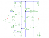
See below how I've eliminated the distortion of the drivers. Admittedly, it's a quick and dirty solution by using CFP stages and current sources, but nevertheless it gives optimal results.
Also notice that I've slightly adjusted the compensating caps so that the NFB loop in both circuits has the same Ft, 2.8MHz.
For results, see next post.
Cheers, Edmond.
Again, it seems that it should be easy to provide some gain in this HEC output stage where you've gone to CFP drivers which as I've pointed out before should eliminate the need for boosted front end supply. I like to see the two converging as far as complexity goes.
Pete B.
Pete wrote:
Quite right.Certainly, the components in the two designs will have different sensitivities with regard to how they impact distortion, stability and many more system parameters. I'm not going to say which is better since I've not done or seen the analysis, just that they are different.
Bob wrote:
Brian
For me, and I suspect Edmond also, it is a matter of what you mean by a "valid view". If you are saying a model of a system that is not accurate...that is an approximation that is useful in certain circumstances...is a "valid view" then that is one thing. But the Vanderkooy/Lipshitz analysis and, for example, the proof I provided earlier in this thread are exact. I think it is very misleading to suggest all views are equally valid. They are not. And as Edmond rightly points out it can lead to mistakes if the approximate models are not qualified as such.Quite frankly, this is exactly what went through my head about you when you refused to accept that any view of HEC other than your own feedback view had any value.
Brian
Re: Re: Re: Re: Re: hec != hoax ?
Guys - been reading this thread off and on. IMHO the first schematic looks a lot like a closed-loop buffer output stage. It's been around a long time. Another way to look at it is as a composite amplifier. Take Walt Jung's AD823/AD815 line amp and use instead of the AD823 an amp where you can get at the high gain node (you folks call it the VAS?). In fact you can more sensibly compensate it this way.
Edmond Stuart said:
Hi Jan,
I was referring to output stages in isolation. The schematics can be found here:
http://www.diyaudio.com/forums/attachment.php?s=&postid=1356927&stamp=1195651662
Cheers, Edmond.
Guys - been reading this thread off and on. IMHO the first schematic looks a lot like a closed-loop buffer output stage. It's been around a long time. Another way to look at it is as a composite amplifier. Take Walt Jung's AD823/AD815 line amp and use instead of the AD823 an amp where you can get at the high gain node (you folks call it the VAS?). In fact you can more sensibly compensate it this way.
Bob Cordell said:Hi Edmond,
Quite frankly, this is exactly what went through my head about you when you refused to accept that any view of HEC other than your own feedback view had any value.
Vanderkooy and Lipshitz showed the validity of the NFB view of HEC more than 20 years ago, and I have never disputed it as a valid view. I think the alternative circuit you have shown makes a valuable comparison, but there was never a need for you to prove the validity of the NFB view.
Cheers,
Bob
Hi Bob,
We all have our kind of stubborness.
") Some people bluntly deny a particular point of view, other people repeatedly don't listen to arguments and I will never give up if I'm convinced that I'm right.
Some people bluntly deny a particular point of view, other people repeatedly don't listen to arguments and I will never give up if I'm convinced that I'm right.>but there was never a need for you to prove the validity of the NFB view.
If this forum was populated by guys like Vanderkooy and Lipshitz, indeed, there wasn't a need to do that, but regrettable, even right at this moment, there are still guys who don't accept the NFB view.
So I'll repeat in behalf of the unbelievers some phrases from Vanderkooy and Lipshitz :
"input-injected active error feedback schemes...., it is in reality only negative feedback."
"The stability margin is, however, in both cases determined solely by the total loop gain ...., which also determines gain stabilization, distortion reduction and output impedance changes."
It's true, you have never disputed it as a valid view. But that's beside the point. Valid or not, what is it worth form an engineering point of view? What does it reveal, pros as well as cons? The other points of view fail in this respect. If they don't, please correct me.
BTW, you know about the paper of Vanderkooy and Lipshitz and their opinion about error feedback, all that time long. Nevertheless you built a HEC output stage in stead of an ordinary NFB one. Why?
Perhaps of this argument:
Bob Cordell said:One of the nice subtleties about the EC circuit is that the compensation provided by C1 and C2 rolls off the EC feedback while providing a feedforward effect to the forward path, minimizing bandwidth loss and excess phase introduction by the compensation.
I've investigated that too, though the effect is marginal, 4 degrees at 10MHz. But if you think it is really important, you might have a look at my alternative compensation scheme, which also suggest a kind of feed forward (see C1 and C2).
Cheers, Edmond.
Attachments
hec != hoax ?
Hi Pete,
First, thanks for your comments and I agree with almost all of your remarks.
Whether it is really new? No, of course it is not. The principles were invented more than 40 years ago: a simple input stage, VAS and output stage. As a matter of fact, I don't bother if it is new. My only purpose to drops the schematics here was to show that one can get the same performance by means of a simpler arrangement.
Of course, the actual implementations are different, but that's not the only point that several other people tried to make me clear, they also said that the properties are different. It is the latter I disagree with.
Regarding a sensitivity analysis, I'm sure you agree with me that the NFB topology don't need 1% or even 0.1% accurate resistors to comply with the Hawksford balance.
I also welcome references to existing power amp output stage schematics that use my topology, so we all can learn from it.
Cheers, Edmond.
PB2 said:Edmond, let me repeat something that I've stated over and over, clearly while the two implementations may have similar distortion reduction behavior, the implementations are different. This is what several of us have been pointing out to you and others, I tried by pointing out the null control. I'm not saying that I favor a null control, just pointing out that it is an implementation difference.
Now, I'm sure that you're familiar with sensitivity analysis, that is where we consider each component and how deviations from the nominal value impact the amplifier transfer function. Certainly, the components in the two designs will have different sensitivities with regard to how they impact distortion, stability and many more system parameters. I'm not going to say which is better since I've not done or seen the analysis, just that they are different. It is a complex problem and I don't think people should be so dismissive of HEC it lead to your new design after all.
I was aware of the old Tiger designs, and the Brystons which have high local output stage feedback, so yours was not the first implementation. However, yours is different and, based on simulation seems to provide excellent performance so while many here claimed the analogy was obvious (sure for anyone who read the literature, yes I did by the way) there does not seem to be an implementation such as yours in the public domain, to the best of my knowledge. So, it seems that it was not so obvious except in peoples heads. I am pleased that my challenge resulted in your new output stage design.
I am aware that all the pieces in your design have been done before, as some here have pointed out, but your complete design has not as far as I know. I welcome references to existing power amp output stage schematics that use your topology for those who claim it has been done.
Pete B.
Hi Pete,
First, thanks for your comments and I agree with almost all of your remarks.
Whether it is really new? No, of course it is not. The principles were invented more than 40 years ago: a simple input stage, VAS and output stage. As a matter of fact, I don't bother if it is new. My only purpose to drops the schematics here was to show that one can get the same performance by means of a simpler arrangement.
Of course, the actual implementations are different, but that's not the only point that several other people tried to make me clear, they also said that the properties are different. It is the latter I disagree with.
Regarding a sensitivity analysis, I'm sure you agree with me that the NFB topology don't need 1% or even 0.1% accurate resistors to comply with the Hawksford balance.
I also welcome references to existing power amp output stage schematics that use my topology, so we all can learn from it.
Cheers, Edmond.
Re: hec != hoax ?
Edmond,
How would you define "simpler arrangement"? If it's simply component count, I doubt that any practical implementation of this OPS would count significantly lower than a HEC.
Maybe you think in terms of no adjustments required? Then certainly there's an advantage.
You mentioned that the load dependency of the phase lag is almost identical to the HEC OPS. Could you post the curves? I am unable to reproduce this, most likely I'm doing something wrong. This dependency is critical for the OPS stability when driving complex reactive loads.
Finally, you know my position on your "synthetic" approach (that is, "design by simulation only"). You can't really simulate lots of things like noise, parasitic elements impact, component mismatching, temperature and temperature gradient drifts, potential latch-up conditions, etc... I'm not saying there are any special issues with your new OPS, but only that I personally wouldn't dare to proclaim a certain OPS design as a winner in an imaginary competition, unless it was implemented and measured.
I think some people around are irritated by the title of this sub-thread "hec!= hoax?" which suggests that HEC could be a hoax. Mind you, the fact that HEC can be viewed as NFB doesn't make it a hoax, at least not more than "NFB != hoax?".
Edmond Stuart said:
...the same performance by means of a simpler arrangement.
Edmond,
How would you define "simpler arrangement"? If it's simply component count, I doubt that any practical implementation of this OPS would count significantly lower than a HEC.
Maybe you think in terms of no adjustments required? Then certainly there's an advantage.
You mentioned that the load dependency of the phase lag is almost identical to the HEC OPS. Could you post the curves? I am unable to reproduce this, most likely I'm doing something wrong. This dependency is critical for the OPS stability when driving complex reactive loads.
Finally, you know my position on your "synthetic" approach (that is, "design by simulation only"). You can't really simulate lots of things like noise, parasitic elements impact, component mismatching, temperature and temperature gradient drifts, potential latch-up conditions, etc... I'm not saying there are any special issues with your new OPS, but only that I personally wouldn't dare to proclaim a certain OPS design as a winner in an imaginary competition, unless it was implemented and measured.
I think some people around are irritated by the title of this sub-thread "hec!= hoax?" which suggests that HEC could be a hoax. Mind you, the fact that HEC can be viewed as NFB doesn't make it a hoax, at least not more than "NFB != hoax?".
Re: Re: hec != hoax ?
Hi Ovidiu,
As the total number of components, passive and active. I know that one thing is missing at the moment: the bias generator. If you wish to use one with the same properties as in HEC (which is wrong btw), you will need only 2 additional resistors and 1 tranny.
That's right and no need for expensive precision resistor of 0.1%.
OK, here are some unity gain frequencies (Fc) and phase margins (PM) of the NFB loop for various loads
HEC: . . Fc (MHz) PM (deg.)
2 Ohm . . . 2.20 . . . 63
8 Ohm . . . 2.65 . . . 72
32Ohm . . . 2.85 . . . 75
NFB: . . Fc (MHz) PM (deg.)
2 Ohm . . . 2.22 . . . 70
8 Ohm . . . 2.67 . . . 75
32Ohm . . . 2.87 . . . 77
Also the sensitivities to capacitive loads are very close.
I know that simulations have their limitations. You also can't spice the weight, color and odor, but aren't you exaggerating a little bit?
Besides, I'm just comparing the two topologies by means of simulation, little chance of misleading results.
To reassure you, I've also spiced the most important parasitic lead inductances. As for the local Miller loop, in my latest schematic that one is absolute rock stable. Under no circumstances it can oscillate, as the current gain of that loop is below unity.
Finally, there ain't no winner and there isn't an imaginary competition, as both circuits are equivalent. That's the whole point.
First, there are a lot of people around here, who claim that NFB degrades the 'sonic integrity', thus implying that NFB is a hoax. Should we feel irritated by them? I don't think so.
Second, HEC has already been debunked by others. Notable among them are Vanderkooy and Lipshitz. So how on earth can my subtitle be irritating?
Cheers, Edmond.
syn08 said:Edmond,
How would you define "simpler arrangement"? If it's simply component count, I doubt that any practical implementation of this OPS would count significantly lower than a HEC.
Hi Ovidiu,
As the total number of components, passive and active. I know that one thing is missing at the moment: the bias generator. If you wish to use one with the same properties as in HEC (which is wrong btw), you will need only 2 additional resistors and 1 tranny.
Maybe you think in terms of no adjustments required? Then certainly there's an advantage.
That's right and no need for expensive precision resistor of 0.1%.
You mentioned that the load dependency of the phase lag is almost identical to the HEC OPS. Could you post the curves? I am unable to reproduce this, most likely I'm doing something wrong. This dependency is critical for the OPS stability when driving complex reactive loads.
OK, here are some unity gain frequencies (Fc) and phase margins (PM) of the NFB loop for various loads
HEC: . . Fc (MHz) PM (deg.)
2 Ohm . . . 2.20 . . . 63
8 Ohm . . . 2.65 . . . 72
32Ohm . . . 2.85 . . . 75
NFB: . . Fc (MHz) PM (deg.)
2 Ohm . . . 2.22 . . . 70
8 Ohm . . . 2.67 . . . 75
32Ohm . . . 2.87 . . . 77
Also the sensitivities to capacitive loads are very close.
Finally, you know my position on your "synthetic" approach (that is, "design by simulation only"). You can't really simulate lots of things like noise, parasitic elements impact, component mismatching, temperature and temperature gradient drifts, potential latch-up conditions, etc... I'm not saying there are any special issues with your new OPS, but only that I personally wouldn't dare to proclaim a certain OPS design as a winner in an imaginary competition, unless it was implemented and measured.
I know that simulations have their limitations. You also can't spice the weight, color and odor, but aren't you exaggerating a little bit?
Besides, I'm just comparing the two topologies by means of simulation, little chance of misleading results.
To reassure you, I've also spiced the most important parasitic lead inductances. As for the local Miller loop, in my latest schematic that one is absolute rock stable. Under no circumstances it can oscillate, as the current gain of that loop is below unity.
Finally, there ain't no winner and there isn't an imaginary competition, as both circuits are equivalent. That's the whole point.
I think some people around are irritated by the title of this sub-thread "hec!= hoax?" which suggests that HEC could be a hoax. Mind you, the fact that HEC can be viewed as NFB doesn't make it a hoax, at least not more than "NFB != hoax?".
First, there are a lot of people around here, who claim that NFB degrades the 'sonic integrity', thus implying that NFB is a hoax. Should we feel irritated by them? I don't think so.
Second, HEC has already been debunked by others. Notable among them are Vanderkooy and Lipshitz. So how on earth can my subtitle be irritating?
Cheers, Edmond.
Re: Re: Re: hec != hoax ?
I somehow doubt that two resistors and one tranny could provide three different bias voltages, bias current adjustment and thermal compensation.
Thanks, I'll look into this.
I wouldn't put the e.g. the component mismatch impact or potential thermal issues on the same range with the odor of the PCB.
Which is entirely correct, but then I would change the conclusion to something like: "The simulated performance of the HEC and NFB output stages are similar."
I think you simulated what you think are the most important parasitic elements. Which does not necessary match what is going to happen on a PCB.
Which boils down to my ultimate problem with simulations: the lack of an analytical understanding of a circuit functionality. I am really freaking out when I see how easy it is in simulations to e.g. switch a compensation cap connection between two point with signals in opposite phase and not really understanding anything more than what my tool is telling me. I personally need to "visualize" a circuit as much as possible through a story board (or at best equations), be able to identify the high impedance nodes, identify NFB types (voltage/current in/out), be able to write and proof analytic design rules, be able to elaborate simplified circuit models and understand their limitations, be able to indentify critical signal paths and then extract rules for designing the implementation, etc... Call me old fashion, but that's the world I am comfortable in, at least to a certain degree of complexity where a pure analytical approach becomes impossible. In such circumstances, the best I can do is to stay as conservative as possible and refrain from drawing conclusions until an implementation is available. And if simulation results are against my common sense, I am having problems in blindly trusting the number cruncher.
Don't take me wrong: I am not claiming that an analytical approach can be anytime better than simulations, in terms of precision. I'm talking here about gaining knowledge, not about crunching numbers.
Edmond Stuart said:
Hi Ovidiu,
As the total number of components, passive and active. I know that one thing is missing at the moment: the bias generator. If you wish to use one with the same properties as in HEC (which is wrong btw), you will need only 2 additional resistors and 1 tranny.
I somehow doubt that two resistors and one tranny could provide three different bias voltages, bias current adjustment and thermal compensation.
OK, here are some unity gain frequencies (Fc) and phase margins (PM) of the NFB loop for various loads
HEC: . . Fc (MHz) PM (deg.)
2 Ohm . . . 2.20 . . . 63
8 Ohm . . . 2.65 . . . 72
32Ohm . . . 2.85 . . . 75
NFB: . . Fc (MHz) PM (deg.)
2 Ohm . . . 2.22 . . . 70
8 Ohm . . . 2.67 . . . 75
32Ohm . . . 2.87 . . . 77
Also the sensitivities to capacitive loads are very close.
Thanks, I'll look into this.
I know that simulations have their limitations. You also can't spice the weight, color and odor, but aren't you exaggerating a little bit?
I wouldn't put the e.g. the component mismatch impact or potential thermal issues on the same range with the odor of the PCB.
Besides, I'm just comparing the two topologies by means of simulation, little chance of misleading results.
Which is entirely correct, but then I would change the conclusion to something like: "The simulated performance of the HEC and NFB output stages are similar."
To reassure you, I've also spiced the most important parasitic lead inductances.
I think you simulated what you think are the most important parasitic elements. Which does not necessary match what is going to happen on a PCB.
Which boils down to my ultimate problem with simulations: the lack of an analytical understanding of a circuit functionality. I am really freaking out when I see how easy it is in simulations to e.g. switch a compensation cap connection between two point with signals in opposite phase and not really understanding anything more than what my tool is telling me. I personally need to "visualize" a circuit as much as possible through a story board (or at best equations), be able to identify the high impedance nodes, identify NFB types (voltage/current in/out), be able to write and proof analytic design rules, be able to elaborate simplified circuit models and understand their limitations, be able to indentify critical signal paths and then extract rules for designing the implementation, etc... Call me old fashion, but that's the world I am comfortable in, at least to a certain degree of complexity where a pure analytical approach becomes impossible. In such circumstances, the best I can do is to stay as conservative as possible and refrain from drawing conclusions until an implementation is available. And if simulation results are against my common sense, I am having problems in blindly trusting the number cruncher.
Don't take me wrong: I am not claiming that an analytical approach can be anytime better than simulations, in terms of precision. I'm talking here about gaining knowledge, not about crunching numbers.
Re: Re: Re: Re: hec != hoax ?
Hi Ovidiu,
Admittedly, for an accurate bias generator we need more components, but the same applies to the Hawksford scheme. His simple temperature compensation is only valid in combination with Darlingtons. In case of separate drivers and/or MOSFET output devices, each stage needs their own compensation as they are operating at different temperatures and have (most likely) different temperature coefficients.
Of course I mean just that. The whole discussion is focused on theoretical aspects in the first place.........
and a practical implementation is (of course) another story, although I don't foresee more or fundamental other complications different from HEC.
OK, we have a different approach, never mind. I like to play with my simulator and if I find something that works, then I'm asking myself why it works. That's a fast way to discover new possibilities and it's fun (at least, if you have a user friendly simulator). Besides, if one is well aware of the shortcomings and pitfalls of a simulator, this approach is far less prone to erroneous conclusions than our own brain.
Turning back to the compensation cap, I suppose you have no problem with connecting it between the base and collector of Q5, as it is an ordinary Miller compensation.
Now, ground the input and inject a current either into the base of Q5 or into the emitter of Q2 and you will see that in both cases the signal at the output has the same phase and magnitude.
Maybe the circuit is misleading at first glance, because the emitter of Q2, having a much lower impedance than the collector of Q5, looks like an output in stead of an input. However, from a (Miller) feedback point of view, that's not the case.
I hope you will accept my explanation.
Cheers, Edmond.
syn08 said:I somehow doubt that two resistors and one tranny could provide three different bias voltages, bias current adjustment and thermal compensation.
Hi Ovidiu,
Admittedly, for an accurate bias generator we need more components, but the same applies to the Hawksford scheme. His simple temperature compensation is only valid in combination with Darlingtons. In case of separate drivers and/or MOSFET output devices, each stage needs their own compensation as they are operating at different temperatures and have (most likely) different temperature coefficients.
Which is entirely correct, but then I would change the conclusion to something like: "The simulated performance of the HEC and NFB output stages are similar."
Of course I mean just that. The whole discussion is focused on theoretical aspects in the first place.........
I think you simulated what you think are the most important parasitic elements. Which does not necessary match what is going to happen on a PCB.
and a practical implementation is (of course) another story, although I don't foresee more or fundamental other complications different from HEC.
Which boils down to my ultimate problem with simulations: the lack of an analytical understanding of a circuit functionality. I am really freaking out when I see how easy it is in simulations to e.g. switch a compensation cap connection between two point with signals in opposite phase and not really understanding anything more than what my tool is telling me. I personally need to "visualize" a circuit as much as possible through a story board (or at best equations), be able to identify the high impedance nodes, identify NFB types (voltage/current in/out), be able to write and proof analytic design rules, be able to elaborate simplified circuit models and understand their limitations, be able to indentify critical signal paths and then extract rules for designing the implementation, etc... Call me old fashion, but that's the world I am comfortable in, at least to a certain degree of complexity where a pure analytical approach becomes impossible. In such circumstances, the best I can do is to stay as conservative as possible and refrain from drawing conclusions until an implementation is available. And if simulation results are against my common sense, I am having problems in blindly trusting the number cruncher.
Don't take me wrong: I am not claiming that an analytical approach can be anytime better than simulations, in terms of precision. I'm talking here about gaining knowledge, not about crunching numbers.
OK, we have a different approach, never mind. I like to play with my simulator and if I find something that works, then I'm asking myself why it works. That's a fast way to discover new possibilities and it's fun (at least, if you have a user friendly simulator). Besides, if one is well aware of the shortcomings and pitfalls of a simulator, this approach is far less prone to erroneous conclusions than our own brain.
Turning back to the compensation cap, I suppose you have no problem with connecting it between the base and collector of Q5, as it is an ordinary Miller compensation.
Now, ground the input and inject a current either into the base of Q5 or into the emitter of Q2 and you will see that in both cases the signal at the output has the same phase and magnitude.
Maybe the circuit is misleading at first glance, because the emitter of Q2, having a much lower impedance than the collector of Q5, looks like an output in stead of an input. However, from a (Miller) feedback point of view, that's not the case.
I hope you will accept my explanation.
Cheers, Edmond.
Re: Re: Re: hec != hoax ?
Maybe you'll think I'm arguing over semantics here, but the word "equivalent" is rather strong. A year ago in this thread, it was shown that EC is equivalent to a 2 degree-of-freedom (2DOF) feedback system. I understand and agree with that completely. But the comparisons here seem to be asserting that a 1DOF feedback system is equivalent to a 2DOF feedback system. You've shown quite well that the two circuits can have almost identical stability and distortion characteristics. But is that all there is to it, as far as equivalence is concerned?
Consider a single-loop feedback system in which the feedback factor is frequency-independent. If the phase margin is near 90 degrees, the closed-loop bandwidth of the circuit is equal to the unity loop gain frequency of the system.
Now consider an EC system that wraps around a unity gain source follower circuit whose bandwidth is, say, 10 MHz. Take that series RC circuit that compensates the EC loop and replace it with a 1F capacitor. What's the closed-loop bandwidth of the system? Clearly, it's still 10 MHz. Yet the unity loop gain frequency of the EC loop is extremely small. In fact, you can change the frequency compensation of the EC loop all over the place and still get a closed loop bandwidth of 10 MHz. So, for the sake of stability with reactive loads, you might make the unity loop gain frequency of the EC loop, say, 1 MHz. You'll still have a bandwidth of 10 MHz, though you may see some small second-order effects in the closed loop frequency response due to the freq comp of the EC.
One can conclude from this that EC allows trading off stability and distortion without changing the closed-loop bandwidth significantly. This is useful if the unity loop gain frequency of the overall amplifier itself is large (like the 2 MHz number of Bob's amp). Single-loop feedback systems don't have this freedom, as the unity loop gain frequency and the closed-loop bandwidth are coupled variables. The additional degree of freedom in the EC feedback structure gives an additional degree of freedom in the design.
That said, it doesn't appear that Edmond's circuit is strictly a 1DOF feedback system though. The fact that the series RC feeds back to the emitter, rather than the collector of the input transistor might be making the closed-loop bandwidth larger than the unity loop gain frequency. I don't know. It does seem to be a multiple feedback loop system. If this is occurring, then it would be a really good thing to have an analytical model of this to get a general idea of how to exploit this technique. In that sense, I agree completely with Ovidiu's concerns about simulation vs. hand analysis - even though I'm a big fan of simulations.
Edmond Stuart said:Finally, there ain't no winner and there isn't an imaginary competition, as both circuits are equivalent.
Maybe you'll think I'm arguing over semantics here, but the word "equivalent" is rather strong. A year ago in this thread, it was shown that EC is equivalent to a 2 degree-of-freedom (2DOF) feedback system. I understand and agree with that completely. But the comparisons here seem to be asserting that a 1DOF feedback system is equivalent to a 2DOF feedback system. You've shown quite well that the two circuits can have almost identical stability and distortion characteristics. But is that all there is to it, as far as equivalence is concerned?
Consider a single-loop feedback system in which the feedback factor is frequency-independent. If the phase margin is near 90 degrees, the closed-loop bandwidth of the circuit is equal to the unity loop gain frequency of the system.
Now consider an EC system that wraps around a unity gain source follower circuit whose bandwidth is, say, 10 MHz. Take that series RC circuit that compensates the EC loop and replace it with a 1F capacitor. What's the closed-loop bandwidth of the system? Clearly, it's still 10 MHz. Yet the unity loop gain frequency of the EC loop is extremely small. In fact, you can change the frequency compensation of the EC loop all over the place and still get a closed loop bandwidth of 10 MHz. So, for the sake of stability with reactive loads, you might make the unity loop gain frequency of the EC loop, say, 1 MHz. You'll still have a bandwidth of 10 MHz, though you may see some small second-order effects in the closed loop frequency response due to the freq comp of the EC.
One can conclude from this that EC allows trading off stability and distortion without changing the closed-loop bandwidth significantly. This is useful if the unity loop gain frequency of the overall amplifier itself is large (like the 2 MHz number of Bob's amp). Single-loop feedback systems don't have this freedom, as the unity loop gain frequency and the closed-loop bandwidth are coupled variables. The additional degree of freedom in the EC feedback structure gives an additional degree of freedom in the design.
That said, it doesn't appear that Edmond's circuit is strictly a 1DOF feedback system though. The fact that the series RC feeds back to the emitter, rather than the collector of the input transistor might be making the closed-loop bandwidth larger than the unity loop gain frequency. I don't know. It does seem to be a multiple feedback loop system. If this is occurring, then it would be a really good thing to have an analytical model of this to get a general idea of how to exploit this technique. In that sense, I agree completely with Ovidiu's concerns about simulation vs. hand analysis - even though I'm a big fan of simulations.
Re: Re: Re: Re: hec != hoax ?
Hi Andy,
You've raised very interesting points, in particular the degree-of-freedom issue. I like such an analytical approach.
Regarding my circuit, you are right, it isn't strictly an 1DOF system, as also in this case the closed-loop bandwidth isn't reduced by increasing the compensating caps.
The small gain bubble (0.9dB) at about 3.5MHz is intriguing and I've not yet an adequate explanation for this phenomenon. Is it a parasitic effect? Perhaps you didn't noticed, but I have reported the same effect in Bob's output stage when the 'auxiliary' compensation cap C10 (39pF) is removed.
Cheers, Edmond.
andy_c said:Maybe you'll think I'm arguing over semantics here, but the word "equivalent" is rather strong. A year ago in this thread, it was shown that EC is equivalent to a 2 degree-of-freedom (2DOF) feedback system. I understand and agree with that completely. But the comparisons here seem to be asserting that a 1DOF feedback system is equivalent to a 2DOF feedback system. You've shown quite well that the two circuits can have almost identical stability and distortion characteristics. But is that all there is to it, as far as equivalence is concerned?
Consider a single-loop feedback system in which the feedback factor is frequency-independent. If the phase margin is near 90 degrees, the closed-loop bandwidth of the circuit is equal to the unity loop gain frequency of the system.
Now consider an EC system that wraps around a unity gain source follower circuit whose bandwidth is, say, 10 MHz. Take that series RC circuit that compensates the EC loop and replace it with a 1F capacitor. What's the closed-loop bandwidth of the system? Clearly, it's still 10 MHz. Yet the unity loop gain frequency of the EC loop is extremely small. In fact, you can change the frequency compensation of the EC loop all over the place and still get a closed loop bandwidth of 10 MHz. So, for the sake of stability with reactive loads, you might make the unity loop gain frequency of the EC loop, say, 1 MHz. You'll still have a bandwidth of 10 MHz, though you may see some small second-order effects in the closed loop frequency response due to the freq comp of the EC.
One can conclude from this that EC allows trading off stability and distortion without changing the closed-loop bandwidth significantly. This is useful if the unity loop gain frequency of the overall amplifier itself is large (like the 2 MHz number of Bob's amp). Single-loop feedback systems don't have this freedom, as the unity loop gain frequency and the closed-loop bandwidth are coupled variables. The additional degree of freedom in the EC feedback structure gives an additional degree of freedom in the design.
That said, it doesn't appear that Edmond's circuit is strictly a 1DOF feedback system though. The fact that the series RC feeds back to the emitter, rather than the collector of the input transistor might be making the closed-loop bandwidth larger than the unity loop gain frequency. I don't know. It does seem to be a multiple feedback loop system. If this is occurring, then it would be a really good thing to have an analytical model of this to get a general idea of how to exploit this technique. In that sense, I agree completely with Ovidiu's concerns about simulation vs. hand analysis - even though I'm a big fan of simulations.
Hi Andy,
You've raised very interesting points, in particular the degree-of-freedom issue. I like such an analytical approach.
Regarding my circuit, you are right, it isn't strictly an 1DOF system, as also in this case the closed-loop bandwidth isn't reduced by increasing the compensating caps.
The small gain bubble (0.9dB) at about 3.5MHz is intriguing and I've not yet an adequate explanation for this phenomenon. Is it a parasitic effect? Perhaps you didn't noticed, but I have reported the same effect in Bob's output stage when the 'auxiliary' compensation cap C10 (39pF) is removed.
Cheers, Edmond.
Re: Re: Re: Re: Re: hec != hoax ?
That's an interesting and useful property, and one that's not at all obvious (to me at least) by inspecting the circuit.
Is it safe to assume that the final circuit you're referring to is the one in this post? I recall that some earlier circuits you posted had four compensation capacitors total, as opposed to two in that version. Also, I think one of them took the feedback off the driver emitter, while this one is from the "VAS" collector.
Edmond Stuart said:Regarding my circuit, you are right, it isn't strictly an 1DOF system, as also in this case the closed-loop bandwidth isn't reduced by increasing the compensating caps.
That's an interesting and useful property, and one that's not at all obvious (to me at least) by inspecting the circuit.
Is it safe to assume that the final circuit you're referring to is the one in this post? I recall that some earlier circuits you posted had four compensation capacitors total, as opposed to two in that version. Also, I think one of them took the feedback off the driver emitter, while this one is from the "VAS" collector.
Re: Re: Re: Re: hec != hoax ?
Now, this description is something I can live and work with
Which is (otherwise put) exactly my original concern when I originally saw this new OPS schematic, and hence my confusion as of how is this thing really working? Can it be modelled as multiple FB loops? Or as a feedforward compensation schema? Edmond tried to persuade me (with good arguments) that "it doesn't matter" which, being against my common sense, ultimately left me in the same state as Andy's "I don't know".
I have attempted some manual analysis and found that even the open loop gain is hard to define precisely, as long as it depends on the active devices parameters, other than gm, instead of on gm and, as much as possible, some external passive components only. Which is to me a big nono, I don't like the idea of the open loop gain changing significantly when e.g. replacing a tranny with one having a lower Early voltage. Maybe such changes are significant for the closed loop performance, or maybe not, I don't know.
andy_c said:
Maybe you'll think I'm arguing over semantics here, but the word "equivalent" is rather strong.
<snip>
Now, this description is something I can live and work with
That said, it doesn't appear that Edmond's circuit is strictly a 1DOF feedback system though. The fact that the series RC feeds back to the emitter, rather than the collector of the input transistor might be making the closed-loop bandwidth larger than the unity loop gain frequency.
Which is (otherwise put) exactly my original concern when I originally saw this new OPS schematic, and hence my confusion as of how is this thing really working? Can it be modelled as multiple FB loops? Or as a feedforward compensation schema? Edmond tried to persuade me (with good arguments) that "it doesn't matter" which, being against my common sense, ultimately left me in the same state as Andy's "I don't know".
I have attempted some manual analysis and found that even the open loop gain is hard to define precisely, as long as it depends on the active devices parameters, other than gm, instead of on gm and, as much as possible, some external passive components only. Which is to me a big nono, I don't like the idea of the open loop gain changing significantly when e.g. replacing a tranny with one having a lower Early voltage. Maybe such changes are significant for the closed loop performance, or maybe not, I don't know.
Re: Re: Re: Re: Re: Re: hec != hoax ?
Hi Andy,
Yes, this post
Cheers, Edmond.
andy_c said:That's an interesting and useful property, and one that's not at all obvious (to me at least) by inspecting the circuit.
Is it safe to assume that the final circuit you're referring to is the one in this post? I recall that some earlier circuits you posted had four compensation capacitors total, as opposed to two in that version. Also, I think one of them took the feedback off the driver emitter, while this one is from the "VAS" collector.
Hi Andy,
Yes, this post
Cheers, Edmond.
Re: Re: Re: Re: Re: Re: Re: hec != hoax ?
Thanks. In a way, this is reminding me of how Bob compensated his amp in the AES article - except this one is using current feedback. IOW, it looks like the transfer function (with input set to zero) starting from the output and ending at the VAS output is that of an integrator with an added zero on the negative real axis. Maybe it is this zero that gives the slight hump in the closed loop gain?
Edmond Stuart said:
Thanks. In a way, this is reminding me of how Bob compensated his amp in the AES article - except this one is using current feedback. IOW, it looks like the transfer function (with input set to zero) starting from the output and ending at the VAS output is that of an integrator with an added zero on the negative real axis. Maybe it is this zero that gives the slight hump in the closed loop gain?
Re: Re: Re: Re: Re: hec != hoax ?
Hi Ovidiu,
Please, don't worry too much about that feed forward thingy, just like the compensation in Bob's implementation, it tends to be more an optical illusion.
Regarding the open loop gain, that is at DC, I would also say, don't worry too much about that, it's the same story as with any other amp or op-amp. As long as this value is much higher than at critical frequencies (e.g. 20kHz) no problem. At these high frequencies, the loop gain is mainly determined by C1 and R2 (or C2 and R3).
Cheers, Edmond.
syn08 said:..............
Which is (otherwise put) exactly my original concern when I originally saw this new OPS schematic, and hence my confusion as of how is this thing really working? Can it be modelled as multiple FB loops? Or as a feedforward compensation schema? Edmond tried to persuade me (with good arguments) that "it doesn't matter" which, being against my common sense, ultimately left me in the same state as Andy's "I don't know".
I have attempted some manual analysis and found that even the open loop gain is hard to define precisely, as long as it depends on the active devices parameters, other than gm, instead of on gm and, as much as possible, some external passive components only. Which is to me a big nono, I don't like the idea of the open loop gain changing significantly when e.g. replacing a tranny with one having a lower Early voltage. Maybe such changes are significant for the closed loop performance, or maybe not, I don't know.
Hi Ovidiu,
Please, don't worry too much about that feed forward thingy, just like the compensation in Bob's implementation, it tends to be more an optical illusion.
Regarding the open loop gain, that is at DC, I would also say, don't worry too much about that, it's the same story as with any other amp or op-amp. As long as this value is much higher than at critical frequencies (e.g. 20kHz) no problem. At these high frequencies, the loop gain is mainly determined by C1 and R2 (or C2 and R3).
Cheers, Edmond.
Re: Re: Re: Re: Re: Re: Re: Re: hec != hoax ?
Hi Andy,
I'm not 100% sure (the circuit is also new for me, you know), but I guess (and hope) that you hit the nail on his head.
Cheers, Edmond.
andy_c said:Thanks. In a way, this is reminding me of how Bob compensated his amp in the AES article - except this one is using current feedback. IOW, it looks like the transfer function (with input set to zero) starting from the output and ending at the VAS output is that of an integrator with an added zero on the negative real axis. Maybe it is this zero that gives the slight hump in the closed loop gain?
Hi Andy,
I'm not 100% sure (the circuit is also new for me, you know), but I guess (and hope) that you hit the nail on his head.
Cheers, Edmond.
Edmond Stuart said:
Hi Bob,
We all have our kind of stubborness.
>but there was never a need for you to prove the validity of the NFB view.
If this forum was populated by guys like Vanderkooy and Lipshitz, indeed, there wasn't a need to do that, but regrettable, even right at this moment, there are still guys who don't accept the NFB view.
So I'll repeat in behalf of the unbelievers some phrases from Vanderkooy and Lipshitz :
"input-injected active error feedback schemes...., it is in reality only negative feedback."
"The stability margin is, however, in both cases determined solely by the total loop gain ...., which also determines gain stabilization, distortion reduction and output impedance changes."
It's true, you have never disputed it as a valid view. But that's beside the point. Valid or not, what is it worth form an engineering point of view? What does it reveal, pros as well as cons? The other points of view fail in this respect. If they don't, please correct me.
BTW, you know about the paper of Vanderkooy and Lipshitz and their opinion about error feedback, all that time long. Nevertheless you built a HEC output stage in stead of an ordinary NFB one. Why?
Perhaps of this argument:
I've investigated that too, though the effect is marginal, 4 degrees at 10MHz. But if you think it is really important, you might have a look at my alternative compensation scheme, which also suggest a kind of feed forward (see C1 and C2).
Cheers, Edmond.
First of all, Vanderkooy and Lipshitz, both good friends of mine, published their analysis of HEC after I presented my original paper at the AES Convention in October, 1982.
Although I was well aware that feedback was involved, and indeed probably was the first to point out that it needed to be compensated, I felt at the time that the original description of the principle by Hawksford, and the particular implementation that it led to, was very valuable. I still do. I think the description lends very good insight, and is not in opposition to the NFB view of it. Those views can live together in peace in spite of your rather narrow objection.
It is nice that you came up with your all-NFB scheme, even though it did in fact take you a couple of iterations to get it to be competitive with the 25-year-old HEC scheme. I might add that the original scheme was arrived at, and provided outstanding performance, without the benefit of SPICE (even though, as you know, I am a strong advocate of the use of SPICE).
That it took 25 years for someone like you to come up with a pure NFB scheme to be competitive with it seems to be somewhat of a testament to the value of the view and the scheme. You have yet to simulate a complete amplifier with your approach much less build one, as far as I know.
What Vanderkooy and Lipshitz said about HEC is correct, but the Devil is in the details of any scheme. The particular implementation that HEC employs is particularly attractive and high-performing. The fact that they showed in theory that it is "only" negative feedback does not take away from the elegance or effectiveness of the scheme, nor was that their intention.
You have done a nice piece of work, but you have not slayed any dragons, nor proved any fraud.
I think that you are so upset about HEC because someone chose to use the term "error correction" in connection with it, violating your personal laws of semantics.
Cheers,
Bob
- Home
- Amplifiers
- Solid State
- Bob Cordell Interview: Error Correction