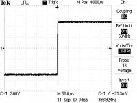
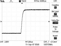
Here're two very preliminary 1kHz and 10kHz squarewave tests of a proto board. This is minus output stage, 0 bias and at only 35V rails so not at all proper operating conditions, but it gives an idea. Transistors were 2SA970/2SC2240 input, 3310 mosfers, 2SA968/2SC2238 predrivers and MJE15032/MJE15033 drivers. R and C values are the same as in the BOM.
Attachments
Re: More pictures
Ok loek here we go.........
very nice indeed PWatts. Yes it gives us an idea and thats not a bad one.
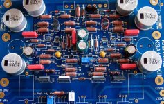
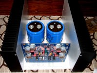
loek said:Hi Flodstroem, it would be nice to see a full body picture here of your stuffed board maybe?
Greetings, Loek
Ok loek here we go.........
PWatts said:Here're two very preliminary 1kHz and 10kHz squarewave tests of a proto board. This is minus output stage, 0 bias and at only 35V rails so not at all proper operating conditions, but it gives an idea. Transistors were 2SA970/2SC2240 input, 3310 mosfers, 2SA968/2SC2238 predrivers and MJE15032/MJE15033 drivers. R and C values are the same as in the BOM.
very nice indeed PWatts. Yes it gives us an idea and thats not a bad one.
Attachments
One thing I can't remember if I've mentioned: the boards were designed exactly according to the originals. The driver transistors' screws were not insulated with a plastic bush i.e. the screws made contact with the collectors. At the bottom of the board, they tightened it with tooth washers, so in effect the collectors made good contact with the power planes directly via the screws. However, this means that the heatsink must be well-insulated. What Krell did was to drill the holes quite a bit larger, and then fit 3mm inside diameter bushes inside the holes to ensure there will be no electrical contact between the screws and heatsink. The easiest though is to simply use Nylon screws of course.
PWatts said:One thing I can't remember if I've mentioned: the boards were designed exactly according to the originals. The driver transistors' screws were not insulated with a plastic bush i.e. the screws made contact with the collectors. At the bottom of the board, they tightened it with tooth washers, so in effect the collectors made good contact with the power planes directly via the screws. However, this means that the heatsink must be well-insulated. What Krell did was to drill the holes quite a bit larger, and then fit 3mm inside diameter bushes inside the holes to ensure there will be no electrical contact between the screws and heatsink. The easiest though is to simply use Nylon screws of course.
I dont think Nylon screws are the best solution for this application though its seems to be the easiest. Nylon screws do change their strange when mounted in a hot environment, they could even melt down if to hot. Best solution as I can see it would be to use the original "Krell method" As insulator bushes you can use a flexible urethan/glass fiber reinforced tubing. Those type of insulating tubes could withstand several hundreds of °C.
And also could be easily cut with the help av a scissor or a wire hand cutter.
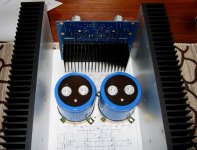
As you maybe could observe at my boards, the pre-drivers are fully insulated types and for those transistors there is no need for insulating hard wares.
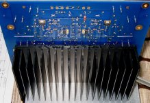
The heat sink for the drivers (on rear side of main board) will be fully grounded by the mounting screws from the bottom chassis. Because of that the driver transistors had to be mounted with all necessary insulating hard wares.
Regards
analogair said:By the way, Nice Heatsinks Flodstroem
Yhe isnt they nice, Remember there was a GB for those heat sinks and many of them was shipped to Denmark, hehe. (how many was on your lot Toni?)
I still have three matched pairs.AndrewT said:I have three pair of CRD E series current reg diodes (rapid 47-2606).
matched at 2.9mA, 2.9mA & 3.1mA.
Letter post in the UK is cheap.
Flodstroem said:
........Remember there was a GB for those heat sinks and many of them was shipped to Denmark, hehe. (how many was on your lot Toni?)
20 pieces.
They where for Steenoe my brother and I.
Nobody who have a set of the Krell KSA 100mkII Clone PCB, like the ones Flodstroem uses, for sale ?

For those that want to know I did track down John at Victoria Magnetics. Aside from his Victoria Magnetics duties he also runs the service department for Smart Devices. If anyone here wants custom made toroids for this project go ahead contact John directly at Smart Devices service department. 1-800-45-smart
Mark
Mark
Mark A. Gulbrandsen said:For those that want to know I did track down John at Victoria Magnetics. Aside from his Victoria Magnetics duties he also runs the service department for Smart Devices. If anyone here wants custom made toroids for this project go ahead contact John directly at Smart Devices service department. 1-800-45-smart
Mark
Hi Mark,
and to all members of this Clone-project:
Im trying this: I have sent John a long letter (e-mail) regarding a custom transformer to see what will be the price quotation. Could you or somebody else come in here and make (if any) suggestions of special electrical and physical data ?
What is most beneficial to order, only one single model (say 2kVA?) or two models, one for mono blocks (1kVA) and one for stereo-amps? Do you member prefer mono-supplies/split supplies (two for a stereo amp) or only one power supply for a stereo-amp?
Regards
Hi,
At that size, 1kVA to 2kVA, there is little difference in regulation.
A dual mono with single 2kVA or two 1kVA will hold up just about the same under load.
The other considerations of channel separation are more important and I suggest you look at single channel capability only.
Lots of copper = low voltage losses and low internal heat and good regulation. Most of my toroids seem to use 3.1A/sqmm of winding (primary and secondary) what about 2.5A/sqmm on the primary and 2A/sqmm on the secondary (does this make sense?).
Electrostatic screen to reduce mains to secondary interference and capacitive coupling introducing mains current onto the power ground.
Guass band to reduce electromagnetic radiation.
Vacuum impreganated core to minimise the risk of core vibration.
second vacuum impregnation of the windings to extract the heat (no air insulation) and reduce risk of windings vibrating. Don't bother with potting nor an attachment fill in the middle.
Design for 50Hz use and tap the primary at 110,115,120 + 110,115,120 to suit all voltages & frequencies worldwide.
A couple or maybe 4 extra low voltage/current windings 2 @ 6Vac and 2 @ 9Vac could cover a lot of build options. Maybe 1A on each giving a DC capability of 500mA from each winding.
Back to the secondaries.
I wired my 4 winding transformer as two parallel (bifillar) sets and used a single 35A bridge. It got too hot to touch in free air without a heatsink. I split the paralleled sets and ran two rectifiers and paralleled the bridge outputs so each bridge is carrying half the current. They now run cold with a small common heatsink connecting the pair of bridges. It will cost a little extra to ask for a quad fillar secondary, it might cost no extra since they will probably choose to wind with thinner guage wire anyway and then internally solder them together. It saves them joining them. 1kVA @ 38Vac needs 4.2sqmm using 3.1A/sqmm. 4.2sqmm = 2.3mm diameter for a bifillar or 1.65mm diameter for quadfillar. At 2A/sqmm the wires would be even bigger (2.9mmdiam & 2.05mmdiam), they are bound to use quadfillar or maybe even more.
Any other spec?
Andrew, thanks for all your comments.
Regarding regulation or channel separation, this isnt an issue right now, but price is. Therefor I must point at the pricing for two 1kVA could be much higher than for a single 2 kVA transformer. There was a zero interest for an original Krell transformer and I think the reason for that was only a to high price.
Im trying to reach a price level where members could accept two transformers (preferably) for their stereo-project but I dont know if this is possible?
All your other specifications are considered and also a part of this price quotation.
I agree to your suggestion regarding mains voltage.
Regarding low voltage windings, yes I could agree to that too but I must check price difference between one or two windings (including center taps, and if this is necessary).
Jozua, I guessed Andrew suggested just that by his point on low voltage/current windings..
All high power secondary windings will be done as "bifillar" windings to achieve good balance between the ±rails
Maybe we should choose a secondary voltage to be 2 x 38-40V including an 2 x 6-9V winding at rated current (approx. 10.4A @ 1 kVA). This idea would support not only the Krell KSA 100 project but also other project with class A or AB design up to approx. 350W of power output capability (@ 8 ohm) and 700W (@ 4 ohm).
One reason for this idea would be that we could get more people interested in a GB, not only those who are involved in this project, but also other DiY members.
Its great with feedback, thats for sure. Any more ideas for a custom transformer?
Regards
- Home
- Amplifiers
- Solid State
- Krell KSA 100mkII Clone