dave_gerecke said:So John's previous statement raises a question, if you are using a class A amp that generates a lot of heat, but you use the heat productively, does that make it more efficient?!
Yes, but not very convenient if the room thermostat turns the Amp off at a critical listening point
PMA said:My power amp takes 200W at idle. Fine in winter, but suggestion needed how to use that energy in summer
Plumb it in to your hot water tank and heat the water ?
PMA said:
Good point. I will show a few.
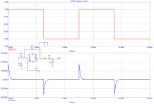
PMA said:square
And your point is?
BTW, if you want to simulate the output impedance, you'd better use a current source connected to the output.
syn08 said:
$80
You certainly don't like JFETs, arent you
That option is in the cards; but I'm thinking more and more about cooling the thing. A 1x1 inch Peltier device is cooling 10W at 70 degrees centigrades under the ambient and costs $20. Have to figure out what to do with the heat and condensation, though... Soo this thing is going to look like a power amp, with finned heatsinks, etc...

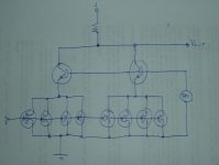
I just had one of those ideas that is either really clever or really dumb.
If you can't get more than 4 of those JFET's to operate directly in parallel without oscillating due to high net gm, then perhaps, if I'm not missing something here, this may be a solution. Add as many quads as your heart desires:
????
Cheers,
Glen
Attachments
As long as the En is constant over frew, you can do like you say, but for a JFET for ex where En is not constant, one has to integrate
either numercally or mathematically over the freq range to get the total input noise.
Easy to do in either MathCAD or a simulation software or can be done by hand
Sigurd
either numercally or mathematically over the freq range to get the total input noise.
Easy to do in either MathCAD or a simulation software or can be done by hand
Sigurd
john curl said:The 1 Hz bandwidth should not bother you. It is easy to average over a much larger bandwidth by multiplying over the square root of the larger bandwidth.
For example, a 10,000Hz bandwidth looks like 100 times more noise than a 1 Hz bandwidth. IF everything is normalized to 1 Hz, it is easy to do piecemeal approximations, because the noise may be worse at the end of the bands, and have to be totaled separately to get an accurate evaluation of what you are going to get just from the data sheet.
Another suggestion for a sub 0.4nV/rtHz input stage for a MC RIAA amp is this one.
en = 0.38nV/rtHz @ 1kHz
Total noise flat from 20-20k: 52nVrms
SNR = 80dB flat 20-20k re 500uV
en for SK170BL (8m Idss) = 0.9nV/rtHz at 1kHz
en for SJ74BL (7.8m Idss) = 0.75nV/rtHz at 1kHz
There is one practical problem, though.....
SIgurd
en = 0.38nV/rtHz @ 1kHz
Total noise flat from 20-20k: 52nVrms
SNR = 80dB flat 20-20k re 500uV
en for SK170BL (8m Idss) = 0.9nV/rtHz at 1kHz
en for SJ74BL (7.8m Idss) = 0.75nV/rtHz at 1kHz
There is one practical problem, though.....
SIgurd
john curl said:What SYN-08 has shown here is what can be done to make an ultra low noise MC FET input phono stage.
This number has been achieved before by Japanese designs back in the late '70's and early 80's using bipolar devices, but they never sounded as good as a fet design. It might be RFI sensitivity and dynamic range that makes the difference.
This topic still remains inside the Blowtorch thread, because an earlier version of this input stage is in the Blowtorch picture (11) and also is in my own personal unit.
I made two mistakes in the original design that is more than 25 years old now. One important one was where I fed back the servo output back to the input. Even though I used a 500/1 divider to reduce noise injection, I, unfortunately got a bad batch of LF411 fet input op amps that added excessive low frequency noise to the input. The measurements of the Vendetta Research noise done by 'Stereophile' appears to show this problem. This was an early unit that used the LF411, as it was about the only device available. Later, I changed to the AD711 (a Scott Wurcer upgrade to the LF411), exclusively, and removed most of the problem. However, I don't use the same servo connection anymore in my latest design, so I hope to have removed any significant 1/f contribution to the latest design. Even 500/1 is not really enough.
Secondly, I used the equivalent of a 10 ohm wire wound pot at the input that did 3 things: 1. bias control of the fets, 2. a way to 2'nd harmonic distortion cancel the slightly different Gm of the N and P parts principally due to mobility differences between electrons and holes, 3. to provide a ground return for the servo.
As the servo doesn't have to be there, anymore, then the resistors can be reduced to virtually nothing, much as SYN08 has done. The input resistors (pot) added only 2.5 ohms extra noise anyway, but improvement can be made, if the effective resistor value is reduced.
These are not easy circuits to build. They require excessive matching and noise screening to do it right. A production nightmare!
Attachments
Sigurd Ruschkow said:Another suggestion for a sub 0.4nV/rtHz input stage for a MC RIAA amp is this one.
en = 0.38nV/rtHz @ 1kHz
Total noise flat from 20-20k: 52nVrms
SNR = 80dB flat 20-20k re 500uV
en for SK170BL (8m Idss) = 0.9nV/rtHz at 1kHz
en for SJ74BL (7.8m Idss) = 0.75nV/rtHz at 1kHz
There is one practical problem, though.....
SIgurd
Sigurd,
You asked in a private email a very good question regarding noise simulation and the JFET parameters. Since this could be of a wider interest I'm posting the response here.
The following applies to PSPICE; for other Berkley Spice clones, you have to doublecheck with your provider's documentation.
The JFET noise model is shared with the GaAsFET model. All noise sources are current based.
A) The extrinsic noise sources
These are current sources attached to each of the parasitic resistances:
I^2=4*k*T/(R/A)
where R is the parasitic resistance, and A is the device area (default=1)
B) The intrinsic noise sources
The JFET model assumes two noise models: shot and flicker (aka 1/f noise)
Is^2=8*k*T*gm/3 is the shot noise. As you see, not much of a device parameter to adjust here
If^2=Kf*Id^Af/f is the flicker noise. Here, Kf (default=0) and Af (default=1) are model parameters, Id is the drain current and f is the frequency.
Both Is and If are considered in parallel with the gm*Vgs output current generator. They are also considered uncorrelated, therefore the squares simply add to render the total current noise.
As you see, by default the flicker noise generator is considered zero (Kf=0). However, in my 2SK170 model:
*DEVICE=P2SK170, NJF
.subckt P2SK170 D G S
+ params:
+ BETA=59.86m
J_P2SK170 D G S J2SK170
*
.model J2sk170 NJF(Beta={BETA} Rs=4.151 Rd=4.151 Betatce=-.5 Lambda=1.923m
+ Vto=-.5024 Vtotc=-2.5m Cgd=20p M=.3805 Pb=.4746 Fc=.5
+ Cgs=25.48p Isr=84.77p Nr=2 Is=8.477p N=1 Xti=3 Alpha=10u Vk=100
+ Kf=111.3E-18 Af=1)
.ends P2SK170
Kf=111.3e-18 and Af=1 (the default value anyway). I don't have the foggiest idea who created this model and how accurate it is, however it's apparently as easy as matching the measured and modelled results by adjusting Kf
In the BF862 model:
*DEVICE=PBF862, NJF
.SUBCKT PBF862 1 2 3
+ params:
+ BETA=47.80m
JBF862 4 7 6 J_BF862
Ld 1 4 1.1n
Ls 3 6 1.25n
Lg 2 5 0.78n
Rg 5 7 0.535
Cds 1 3 0.0001p
Cgs 2 3 1.05p
Cgd 1 2 0.201p
Co 4 6 0.35092p
*
.model J_BF862 NJF(Beta={BETA} Betatce=-.5 Rd=.8 Rs=7.5000
+ Lambda=37.300E-3 Vto=-.57093 Vtotc=-2.0000E-3 Is=424.60E-12
+ Isr=2.995p N=1 Nr=2 Xti=3 Alpha=-1.0000E-3 Vk=59.97
+ Cgd=7.4002E-12 M=.6015 Pb=.5 Fc=.5 Cgs=8.2890E-12 Kf=87.5E-18
+ Af=1)
.ENDS PBF862
they are assuming and even lower Kf therefore BF862 should apparently have better intrinsic noise performance than 2SK170. However, the extrinsic noise sources are considered as well.
In the real life, BF862 has slightly worse noise performance compared to 2SK170. Which obviously would make you think that the 2SK170 Kf parameter is overestimated.
Unfortunately, setting Kf=0 gives 3nV/rtHz which does not match the experimental value of 2.5nV/rtHz (for sorted devices). Which leads quickly to the conclusion that Rs and Rd in the model are overestimated. If you look at the BF862 model (somehow I trust it more than the 2SK170 model of unknown origin), there is a huge discrepancy between Rd's. Also, from a device design perspective, having Rd=Rs (as in the 2SK170 model) is completely non realistic. But we are already on a slippery path; changing Rs will change other characteristics (including the DC)...
Now, to add insult to injury, the 2SJ74 model has to be tweaked as well.
*DEVICE=P2SJ74, PJF
.subckt P2SJ74 D G S
+ params:
+ BETA=92.12m
J_P2SJ74 D G S J2sj74
*
.model J2sj74 PJF(Beta={BETA} Rs=7.748 Rd=7.748 Betatce=-.5 Lambda=4.464m
+ Vto=-.5428 Vtotc=-2.5m Cgd=85.67p M=.3246 Pb=.3905 Fc=.5
+ Cgs=78.27p Isr=129.8p Nr=2 Is=12.98p N=1 Xti=3 Alpha=10u Vk=100
+ Kf=26.64E-18 Af=1)
.ends P2SJ74
As you see, this assumes a lower intrinsic flicker noise, but larger extrinsic noise, which makes some physical sense, but certainly adjusting all these parameters is very difficult. Honestly, I don't have the appetite to do this.
And finally, remember that even the JFET noise model (with Is and If expressions above) is pretty poor. All in one, you just got a good example as of why the stock Spice is so difficult to trust...
If you have the patience and motivation to adjust the models to better match both the DC and noise measured performances (and that's assuming the AC model is ok, which might be wrong as well) let me know...
Bob Cordell said:Anybody here planning on attending ISSCC in San Francisco?
Scott?
I'll be there.
Cheers,
Bob
Yes, there is some good optical stuff. I'll have to run my latest hair brained idea by you.
See you at happy hour!
syn08 said:
If you have the patience and motivation to adjust the models to better match both the DC and noise measured performances (and that's assuming the AC model is ok, which might be wrong as well) let me know...
Remember the "fudge" factor in the FET noise model comes from integration of the ideal Shockley equations for an ideal symetrical FET. These short channel devices most certainly are not ideal.
Have you seen this paper, they use Toshiba JFETs to prove out the fit to the new model?
Attachments
G.Kleinschmidt said:
I just had one of those ideas that is either really clever or really dumb.
If you can't get more than 4 of those JFET's to operate directly in parallel without oscillating due to high net gm, then perhaps, if I'm not missing something here, this may be a solution. Add as many quads as your heart desires:
????
Cheers,
Glen
I taped this out last month on some left over space on an ExpressPCB run. I was planning then to parallel 8 of them to get my 32x. I'll tell you if it works. I have space for an SMT ferrite bead on each 4 group just in case. They spec at .06 Ohms Rs so that should not be a problem.
scott wurcer said:Have you seen this paper, they use Toshiba JFETs to prove out the fit to the new model?
No, I'll take a look. Thanks!
It is so surprising that people rely on computer simulation, when it can be done with a calculator, easily enough, or even pencil and paper. Just as it is almost impossible for us to write a short note, without a computer, we are becoming overly dependent on computers, AND their circuit models, rather than utilizing direct measurement and data sheet information.
john curl said:It is so surprising that people rely on computer simulation, when it can be done with a calculator, easily enough, or even pencil and paper. Just as it is almost impossible for us to write a short note, without a computer, we are becoming overly dependent on computers, AND their circuit models, rather than utilizing direct measurement and data sheet information.
The answer is IMO easy. Many people just do not care. They are not interested in actual real world results, not interested in listening tests, not interested in direct comparisons. Bedroom armchair theoretical argueing, that is the goal.
PMA, I note your simulation, but I think what we have to look at is the transition between class A and class B in the 797 output stage. This should occur at about .1V out, I should think. This is where the 'action' is musically as well. It is the harmonic series that will be generated, because the load is so low, that worries me.
Right now I am using the same IC, but with an 800 ohm load to do the same job. I'm worried, even though I have 10 times less loading than SYN08 has in his circuit.
Right now I am using the same IC, but with an 800 ohm load to do the same job. I'm worried, even though I have 10 times less loading than SYN08 has in his circuit.
john curl said:Where are accurate models of 1/f noise in these devices below 100Hz? That is what makes the measurement of the circuit difficult, and inconsistent.
I think this is overstated virtually all microphones have noise that rises twice as fast and starting well before 100Hz. LP's also have a lot of low frequency noise we just are not that sensitive to it. I think selecting FET's at 10Hz is a waste of time just to say you have a great unweighted noise spec.
They are rather accurate below 100 Hz. Both for most low noise OPamps and for JFETs. I think I already have shown that in this thread. For OPamps I showed that in PMA's RIAA design thread.
<100
Taking the 1/f noise into account for the design I showed and calculate total 20-20k noise manually - what would you get for total noise 20-20k flat?
Then, let's say I want to have noise A-weighted....and also have the RIAA transfer function added. That will take a fhour or so minimum
to hand calculate. In a simulator it takes only seconds.
Sigurd
john curl said:Where are accurate models of 1/f noise in these devices below 100Hz? That is what makes the measurement of the circuit difficult, and inconsistent.
- Status
- Not open for further replies.
- Home
- Amplifiers
- Solid State
- John Curl's Blowtorch preamplifier