The aim of this project is to build a simple class A monorual amplifier to play music from a CD player to desktop or floor standing speakers. The design at first pass (pun intended) uses a single transistor and minimal components. Initial testing has found that acceptable sound quality is possible, but I need to build the complete amplifier for proper testing.
This project owes much to the thread here: https://www.diyaudio.com/forums/solid-state/178761-single-gain-stage-transistor-amplifier.html
This project owes much to the thread here: https://www.diyaudio.com/forums/solid-state/178761-single-gain-stage-transistor-amplifier.html
A tube pre-amp and a transistor power amp? Is that what it is?
My circuit is based on the first circuit described here:
Bipolar Transistor Cookbook — Part 7 | Nuts & Volts Magazine
With an input capacitor instead of a transformer.
My circuit is based on the first circuit described here:
Bipolar Transistor Cookbook — Part 7 | Nuts & Volts Magazine
With an input capacitor instead of a transformer.
Last edited:
The story so far...
I started out using the TEA 2025 amplifier board sourced from an old PC speaker. This worked fine for a while, and is a temporary case. The LM386 boards were also tested and placed in a temporary enclosure. I then came across a video on how to make an amplifier using the transistor from a CFL bulb. Not being able to open up the bulb, I used the transistor from a mobile phone charger. Finally, in November 2020 I got it working, and have been testing it since, even using the amplifier circuit to play music at fairly low distortion levels.
I started out using the TEA 2025 amplifier board sourced from an old PC speaker. This worked fine for a while, and is a temporary case. The LM386 boards were also tested and placed in a temporary enclosure. I then came across a video on how to make an amplifier using the transistor from a CFL bulb. Not being able to open up the bulb, I used the transistor from a mobile phone charger. Finally, in November 2020 I got it working, and have been testing it since, even using the amplifier circuit to play music at fairly low distortion levels.
Circuit Diagram
Circuit Diagram
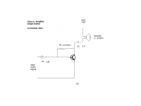
A basic circuit diagram of the amplifier. The configuration shown as tested: I was able to get a 3 Farad capacitor I had in the parts bin, and this improved the sound considerable, louder with less distortion, like the transformer that preceded it. It is a polarized capacitor.
The volume control is not shown, neither is the stereo to mono combiner circuit. The diagram was created using public domain symbols and drawn on Open Office Draw.
Circuit Diagram
A basic circuit diagram of the amplifier. The configuration shown as tested: I was able to get a 3 Farad capacitor I had in the parts bin, and this improved the sound considerable, louder with less distortion, like the transformer that preceded it. It is a polarized capacitor.
The volume control is not shown, neither is the stereo to mono combiner circuit. The diagram was created using public domain symbols and drawn on Open Office Draw.
Attachments
The circuit you showed in post#5 won't work. There is no D.C. path for current to reach the transistor. The capacitor will block current once it has charged. And a 3F capacitor is somewhat large, a supercapacitor. BUt it will eventually charge and stop DC passing, so blocking an audio signal too.
At the very least you need a collector load resistor. If the resistance matches the impedance of the speaker you will only get about 12% efficiency. You won't need 3F to couple the speaker though, perhaps as little as the classic 2.2mF or better still around 22mF.
The resistor will dissipate some heat as will the transistor.
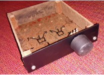
I have been busy trying to cram the circuit board into the enclosure in the image, and it was a losing battle. I remember the advice from long ago "build the circuit first, if you build the case first it may not fit". This is good advice, build complete circuit first. There should be enough space to plug and unplug or connect the wires from the speakers, inputs, and volume control to the connection points on the board.
After using the board outside the case, I got it working, finally. The volume control makes a difference because I can reduce the volume for distortion reduction. I am listening to one CD after another as I cannot stop listening...
Let me be clear about this: The sound is clear at all frequencies at low volumes. At higher output, there is distortion in the low end.
A new case is needed, something that measures at least 6 inches by 8 inches or 15.24 cm by 20.32 cm approximately. So fix the circuit board on the case, then fix the back panel and rear panel with the connectors and connecting wires and plug these into the board.
Nothing like building your own, even if it does not afford 0.001% distortion.
The Circuit
Thanks John, I have checked and rechecked the circuit, and I was just listening to the amplifier just now, for about 90 minutes. The output capacitor is 3F polarized, maybe that has something to do with it.
A collector load resistor - I know it works, but won't it reduce the output volume? Or, if it is a constant current source like a AC DC adapter, will it not matter?
The circuit you showed in post#5 won't work. There is no D.C. path for current to reach the transistor. The capacitor will block current once it has charged. And a 3F capacitor is somewhat large, a supercapacitor. BUt it will eventually charge and stop DC passing, so blocking an audio signal too.
At the very least you need a collector load resistor. If the resistance matches the impedance of the speaker you will only get about 12% efficiency. You won't need 3F to couple the speaker though, perhaps as little as the classic 2.2mF or better still around 22mF.
The resistor will dissipate some heat as will the transistor.
Thanks John, I have checked and rechecked the circuit, and I was just listening to the amplifier just now, for about 90 minutes. The output capacitor is 3F polarized, maybe that has something to do with it.
A collector load resistor - I know it works, but won't it reduce the output volume? Or, if it is a constant current source like a AC DC adapter, will it not matter?
Needs a case
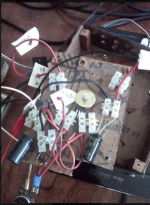
Spending an evening listening to my favorite 1970s CDs on the amplifier ( I call it the November Amp, since I got the circuit working in November) . Amazing sound, clear at 9V V CC and smooth and somewhat detailed. I could listen forever. One channel at the moment, do I go for dual mono or try to build a dual power supply next? Paul (of "Ask Paul") thinks dual mono is better.
The image shows the amplifier in its current testbench state.
Attachments
Last edited:
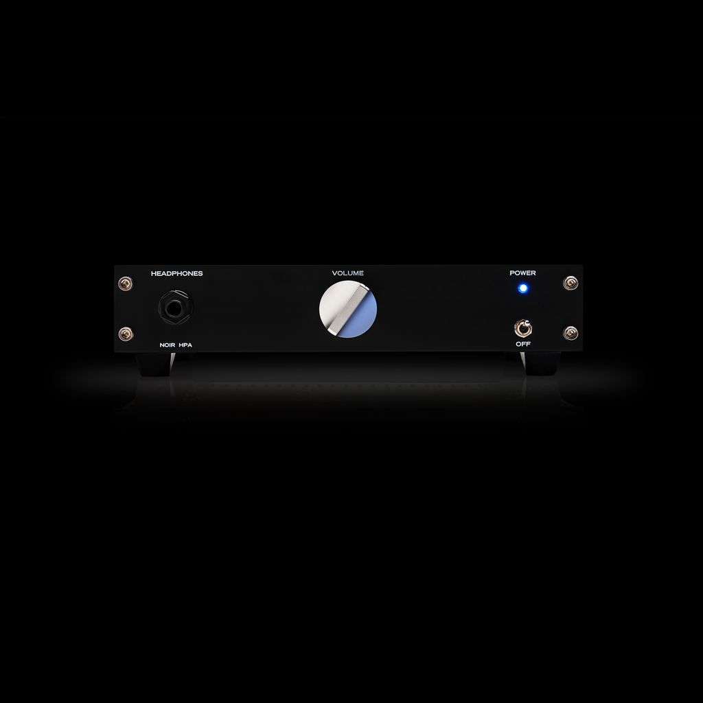
The enclosure is the most important part, it is what the user sees.
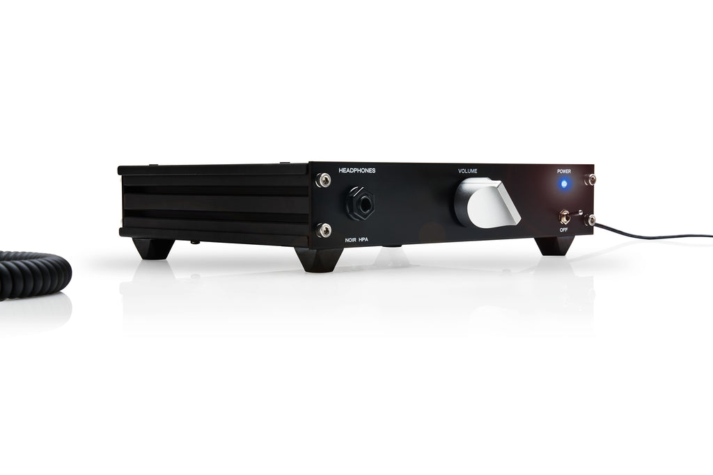
There's a headphone amp kit in the diyAudio Store, which uses a little trick that you may wish to copy. Its front and rear panel are black PCBs, with precision cut edges and precision drill holes, provided at no extra charge by the PCB fab. Logo and lettering for knobs, switches, and connectors is provided using high resolution vector graphics, on the standard PCB silkscreen layer which the PCB fab provides at no extra charge.
All you have to do is lay out the boards for front and rear panel, according to your own specific requirements of size and hole placement. And since they're 2-layer boards, you get Faraday shielding ground planes at no extra cost.
Click on the image files below to see them full size and undistorted.
Member
Joined 2009
Paid Member
Circuit Diagram
A basic circuit diagram of the amplifier. The configuration shown as tested: I was able to get a 3 Farad capacitor I had in the parts bin, and this improved the sound considerable, louder with less distortion, like the transformer that preceded it. It is a polarized capacitor.
The volume control is not shown, neither is the stereo to mono combiner circuit. The diagram was created using public domain symbols and drawn on Open Office Draw.
Fascinating!
If this really the actual circuit built then it certainly will not work over a long time period but it will work for a period of time until the 3F capacitor has charged up sufficiently to the point that there's not enough voltage across the transistor which will start clipping earlier and earlier.
BasicHiFi- as a first estimate the time constant of your circuit is 3F x 4 ohms or 12 seconds. So the capacitor will charge to the supply voltage after about 36s, so your circuit will only be relatively distortion free for less than a minute. It will then clip and give reducing output with time.
To prevent the capacitor charging you will need a collector load resistor, and the available output power will be divided between it and the loudspeaker.
usually the collector load resistor is chosen to be the same as the load, so between 4 and 8 ohms. The operating voltage of the collector should then be one third of the supply.
A constant current source will provide greater output power, but will add another transistor to your circuit as a minimum. The current should be adjusted to set the collector voltage to mid-rail (4.5V) in that case, but best use an oscilloscope to give balanced clipping as the voltage compliance of the current source and saturation voltage of the amplifier transistor will be competing.
To keep the circuit as a single transistor you could consider, at greater expense and weight, using a choke (inductor) load. It will have to be audio grade and specially designed.
An advantage of using a power resistor, constant current source or inductor load is that the speaker can be connected between the ground rail and capacitor rather than the supply.
Ah yes, the Darlington pair. John Audio Tech has a video on how to make one. I am all for greater output. Thanks
Capacitor Check
Ok so one way to test this is to check the voltage across the capacitor in circuit, and with the speaker wire disconnected? Will check and report back.
I listened to 3 albums and stopped with the transistor quite warm to touch.
Fascinating!
If this really the actual circuit built then it certainly will not work over a long time period but it will work for a period of time until the 3F capacitor has charged up sufficiently to the point that there's not enough voltage across the transistor which will start clipping earlier and earlier.
Ok so one way to test this is to check the voltage across the capacitor in circuit, and with the speaker wire disconnected? Will check and report back.
I listened to 3 albums and stopped with the transistor quite warm to touch.
Load Resistor?
So unfortunately I am not familiar with how this circuit work. Transistors - yes, the transistor is like a valve in a water pipe, operated by a smaller water flow (from the input). The transistor is basically a current blocker whose resistance decreases based on the current supplied to the base. This is not linear since the thing will not work at low input currents.
Just to be clear about the 'collector load resistor', here is a diagram to illustrate the item.
Load Resistor Tutorial & Circuits - Junction Transistors - Electronic Hobby Projects
BasicHiFi-
.....
To prevent the capacitor charging you will need a collector load resistor, and the available output power will be divided between it and the loudspeaker.
usually the collector load resistor is chosen to be the same as the load, so between 4 and 8 ohms. The operating voltage of the collector should then be one third of the supply.
...
So unfortunately I am not familiar with how this circuit work. Transistors - yes, the transistor is like a valve in a water pipe, operated by a smaller water flow (from the input). The transistor is basically a current blocker whose resistance decreases based on the current supplied to the base. This is not linear since the thing will not work at low input currents.
Just to be clear about the 'collector load resistor', here is a diagram to illustrate the item.
Load Resistor Tutorial & Circuits - Junction Transistors - Electronic Hobby Projects
There's a headphone amp kit in the diyAudio Store, which uses a little trick that you may wish to copy. ......
Click on the image files below to see them full size and undistorted.
That's one neat amplifier case. The standard to aim for...
Spending an evening listening to my favorite 1970s CDs on the amplifier ( I call it the November Amp, since I got the circuit working in November) . Amazing sound, clear at 9V V CC and smooth and somewhat detailed. I could listen forever. One channel at the moment, do I go for dual mono or try to build a dual power supply next? Paul (of "Ask Paul") thinks dual mono is better.
The image shows the amplifier in its current testbench state.
Can you get me a picture of that 3F Capacitor, Please.. do not see that one in your Picture from here..
Also make a readout with a scope as long it's on the bench table.. it helps a lot to reduce later disappointments when all is finished and it doesn't work as expected anymore..
Thanks
All your circuit requires is a resistor connected between the collector and supply. You can then rearrange the capacitor and loudspeaker to connect to ground.
If you operate the circuit at 9V the collector resistor - let's say 4.7 ohms - will drop about 5V across it. So your transistor will dissipate the remaining 4V multiplied by the current which will be just over 1A =4W. That makes it necessary to use a heatsink, but does not have to be particularly large if you don't mind the transistor getting a little warm (10C/W means a rise of 40 degrees C) but as with all components the cooler you run them the more reliable they will be. I's probably choose a 7C/W heatsink or maybe 5C/W. The resistor on the other hand will be dissipating 5W and should probably be a 10W component in free air or a metal cased 5W on a small heatsink too.
If your circuit really does continue to sound "OK" after several minutes I assume that your massive capacitor is actually leaking some current.
Do you have a meter you can measure the voltage across it when you turn the amplifier on and for a few times at a few minute intervals?
What is the rated voltage? It should be more than your supply voltage, but many supercapacitors are only rated at a few volts (2-3V). You may be exceeding its ratings, causing the leakage.
Last edited:
- Home
- Amplifiers
- Solid State
- Simple Class A Amplifier Project