Sony TA-F3000ES
Ok hopefully someone will spend the time to point me in the right direction. This has all the hallmarks of a short somewhere, but I can't find it.
Maybe someone could also do a "quick" teardown of what the "protection circuits" are doing, The differential amplifier voltages all look ok.. Q506 collector voltage was at zero, and once removed the B+ that was on the bases of Q510 & Q511 became -ve
Blown fuses, Dim bulb tester lights up on applying power
1) Removed MOSFETS Q512, Q513, Q612, Q613. Q512, Q513 were bad.
2) Checked voltages on both channels, all appeared to be good (B+ 34.5V, B- 35V)
3) Replaced all MOSFETS, dim Bulb Tester lit up :-(
4) Removed Q512, Q513 - Amplifier powers up, but Voltage at 1 was 33V, @2 was 7.3V (Base of Q510 & Q511)
5) Removed Q510, Q511 both tested ok, same voltages at same points (In Hindsight don't know why I removed them,
its the voltage going into them that is stressing them out.
6) Removed Q509, tested ok, voltages the same.
so now into the SMD area.
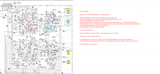
Voltages in RED before removing Q506 - it was showing zero on its collector
Then blow me all the voltages went to B-,
So I'm pretty stuck now, I have an esr tester, and thought C505 might be a problem, since its ESR is 0.12,
but tests ok when removed, albeit still low ESR and -ve voltages still present at Collector Q506 and at points 1 & 2
It could be Q508, but not shorted.
Ok hopefully someone will spend the time to point me in the right direction. This has all the hallmarks of a short somewhere, but I can't find it.
Maybe someone could also do a "quick" teardown of what the "protection circuits" are doing, The differential amplifier voltages all look ok.. Q506 collector voltage was at zero, and once removed the B+ that was on the bases of Q510 & Q511 became -ve
Blown fuses, Dim bulb tester lights up on applying power
1) Removed MOSFETS Q512, Q513, Q612, Q613. Q512, Q513 were bad.
2) Checked voltages on both channels, all appeared to be good (B+ 34.5V, B- 35V)
3) Replaced all MOSFETS, dim Bulb Tester lit up :-(
4) Removed Q512, Q513 - Amplifier powers up, but Voltage at 1 was 33V, @2 was 7.3V (Base of Q510 & Q511)
5) Removed Q510, Q511 both tested ok, same voltages at same points (In Hindsight don't know why I removed them,
its the voltage going into them that is stressing them out.
6) Removed Q509, tested ok, voltages the same.
so now into the SMD area.
Voltages in RED before removing Q506 - it was showing zero on its collector
Then blow me all the voltages went to B-,
So I'm pretty stuck now, I have an esr tester, and thought C505 might be a problem, since its ESR is 0.12,
but tests ok when removed, albeit still low ESR and -ve voltages still present at Collector Q506 and at points 1 & 2
It could be Q508, but not shorted.
Attachments
What I would tend to do at this stage is remove outputs.
Connect Vbe multiplier output back into LTP feedback path.
This gives something that be powered up with bulb in series.
Then you can check voltages around the loop until you find the culprit.
Check bias circuit is working ok.
Connect Vbe multiplier output back into LTP feedback path.
This gives something that be powered up with bulb in series.
Then you can check voltages around the loop until you find the culprit.
Check bias circuit is working ok.
>> What I would tend to do at this stage is remove outputs.
The other two output mosfets?
>> Connect Vbe multiplier output back into LTP feedback path.
 in english?
1) So basically put all transitors back in apart from Mosfets?
+++++++++++++++++++++++++++++++++++
ESP Amplifier Basics - How Audio Amps Work (Part 5)
(The long tailed (or differential) pair is an old circuit, and is used with valves, FETs and BJTs. It was originally designed in the valve era, and provides a means for the comparison of two voltages. The long tailed pair (LTP) is used as the input stage of most opamps, and many (if not most) modern power amplifiers.)
Vbe multiplier output Vbe Multiplier - Multisim Live
God, I have a lot to learn
The other two output mosfets?
>> Connect Vbe multiplier output back into LTP feedback path.
in english? 1) So basically put all transitors back in apart from Mosfets?
+++++++++++++++++++++++++++++++++++
ESP Amplifier Basics - How Audio Amps Work (Part 5)
(The long tailed (or differential) pair is an old circuit, and is used with valves, FETs and BJTs. It was originally designed in the valve era, and provides a means for the comparison of two voltages. The long tailed pair (LTP) is used as the input stage of most opamps, and many (if not most) modern power amplifiers.)
Vbe multiplier output Vbe Multiplier - Multisim Live
God, I have a lot to learn
It is a truly awful diagram the way it is drawn.
My approach would be to build it all up and force a zero bias condition by linking the driver transistor bases so that the FET's can not conduct and then see where its at.
so connect base of Q510 to Q511? When populated they have voltages of +33V and +7.3, instead of 2.5 and -2.6V.
Are the FET's the correct type and genuine?
New ones from cricklewood in UK, Test ok, and from memory with the MOSFETS removed all of the voltages were correct on both channels. Ummmm I will remove mosfets from other channel and check voltages again.
Yes, connect those (I would do it on the left hand side of the 10 ohm resistors).
+33 and +7.3 seems to show you have an open circuit condition (B to E) in either or both driver transistors or more likely the 330 ohm R519 is open or the the 10 ohm are open (depending which side you measured those voltages.
+33 and +7.3 seems to show you have an open circuit condition (B to E) in either or both driver transistors or more likely the 330 ohm R519 is open or the the 10 ohm are open (depending which side you measured those voltages.
Just shows how naive I am, I thought the plus and minus Base voltages on Q510 & Q511 were “generated” by Q206 and Q208. Good learning experiance tho...
I've put it back as it was, and will try tieing the Bases of Q510 & Q511 togeather and see what I get. Thanks for that hint...
(Lost Q206 :-(, pinged onto the floor....damn, will have replacement tomorrow)
I've put it back as it was, and will try tieing the Bases of Q510 & Q511 togeather and see what I get. Thanks for that hint...
(Lost Q206 :-(, pinged onto the floor....damn, will have replacement tomorrow)
It is a truly awful diagram the way it is drawn
I run slightly older Sony ES gear on a daily basis, and generally love the 'neutrality' of them, but I'd have to agree - that's the WORST looking schematic I've looked at in a long time.
Yes, connect those (I would do it on the left hand side of the 10 ohm resistors).
+33 and +7.3 seems to show you have an open circuit condition (B to E) in either or both driver transistors or more likely the 330 ohm R519 is open or the the 10 ohm are open (depending which side you measured those voltages.
Ok put link in you suggested, and restored components including all mosfets. Units doesn't light up the LBT
Q509 BCE 0.22V,0.3V, 1.7V
Q609 BCE 0.6, 2.85 , 0.04
Q514 BCE 0,0,34
Q614 BCE 0,0,34
I've tested C510 and its 330micoF
Q510, Q511, Q509 all test ok (Peak DCA75). R519 is 450ohms in cct, same as R619 from memory, but will check in morning.
Q511 got very hot with the MOSFETS removed,
I think this is above my pay grade
Q511 got very hot with the MOSFETS removed,
I think this is above my pay grade
Hmmm... maybe
Q511 getting hot isn't automatically an issue in itself. If the DC offset up against the positive rail the lower driver will be seeing all the total rail voltage across it plus the current allowed by the constant current sink. So that will make that driver hot and the other cold.
Providing it isn't getting to hot that it fail (sizzling) then you need to look why the offset is high (I'm assuming its high).
It is not an easy one to work on tbh.
"obvious to those well skilled in the art" comes to mind
Where would I measure this on this cct?
(Ahhhh... DC offset = Bias, still where should I measure)
DC offset is not bias
Bias is measured at the two two pin test points shown in grid reference c13 and f13
DC offset is measured at the output with respect to ground.... if the amp isn't working then this is before the speaker output relays. Once the amp is working again , this is simply at the speaker terminals.
Last edited:
ta, will never get there to measure, With the mosfets in it lights up the DBT
This thread has a similar problem.
Interesting comment on both replacing MOSFETS with a restor to complete cct and more importanly measuring the resistors.
Onkyo A-8250 50V on DC Offset transistor - Badcaps Forums
"When an output transistor has failed I temporarily remove all of the main output transistors from the faulty channel. By this I am referring to the large output transistors bolted to the heat sink. Then I connect a 100 ohm 2 watt resistor from B to E terminal pads for each spot on the PC board where an output transistor was originally connected. Do not connect anything to the C terminal pads on PC board. The 100 ohm resistors provide the continuity that is required to get the rest of the amplifier circuit working. And it should be possible to get enough audio output to hear something from the headphone jack.
When the rest of the amplifier circuit is working correctly there will be about 0.5 to 0.6 of DC voltage drop across each of the temporary 100 ohm resistors. And the speaker protectin relay should click in. DC voltage from either end of the temporary 100 ohm resistors should be < 1 volt in reference to negative black speaker terminal output post. This is circuit ground (earth) in most cases."
&
This model and some other Onkyo amplifiers have an unusual architecture for the output stage.
There are 3 low value emitter resistors connected to the output transistors. One or more of these often fail open-circuit after an output transistor shorts out. These resistors are both “flameproof” and “fusible.” They rarely show any visible signs of overheating. Because these 3 resistors are in a series-parallel arrangement it is necessary to disconnect one end of at least one of these 3 resistors in order to check that each individual resistor still has the correct resistance value.
In this circuit the 2 temporary 100 ohm E to B resistors must be connected in place of the 2 large output transistors to test the functionality of the driver circuitry prior to reinstalling new output transistors. This is necessary because the pre-driver and driver stages have no connection to the output line.
ta, will never get there to measure, With the mosfets in it lights up the DBT
With the FET's out of circuit and the driver transistor base's linked you should have no voltage developed across what looks like R519 (330ohm). If you have voltage across that resistor then you have a driver fault.
The feedback loop looks like it will be open circuit with the FET's out so that will cause the voltage on R519 to swing toward a rail but the voltage across the resistor should always be zero.
If you have no voltage across the resistor in that state then there could be an issue with the FET's.
Bringing another into the frame will only confuse matters.
Don't assume any key resistor is ok, take comparative measurements between same points on the working and duff channel
Good advice, Thank you.
It was the suggestion of how to get the transistors out of cct, that something needs to be there to enable the Bias cct, and the need to remove one leg of the resistor to get accurate readings. I have been comparing across the two channels. So what do people think about the suggestion of the need to putting a resistor between
So what do people think about the suggestion of putting a resistor instead of the MOSFETS so that the Bias cct works?
Albeit I was sure voltages were correct before I put the new MOSFETS in. So implied that bias cct works without the MOSFETS in. (Of course I'm doubting myself now)
I swapped the MOSFETS to the other side and the DBT didn't light up, and they still all test ok on Peak DCA75.
Albeit I was sure voltages were correct before I put the new MOSFETS in. So implied that bias cct works without the MOSFETS in. (Of course I'm doubting myself now)
I swapped the MOSFETS to the other side and the DBT didn't light up, and they still all test ok on Peak DCA75.
You don't need the bias controller to work. Linking it out removes it from the equation. The amp (all other things being equal) should work normally in that state but with an increase in distortion.
One valid approach is to see what happens if you remove the FET's but also link the feedback take off point to one or other of the driver outputs. That means linking one of the 0.22 ohms (either) to either emitter of a driver. That restores the loop and the amp should then have no DC offset.
Essentially it would all work as normal but would have no ability to drive a load and would fail if you attempted to do that.
- Home
- Amplifiers
- Solid State
- Sony TA-F3000ES - doing my head in