If Q904 base is 0 v, most likely parts to have failed at 30 years are C912 and/or ZD901. Electrolytic caps are rubber sealed & dry out. NAD didn't buy 30 year e-caps. Zener diodes are known to fail more frequently than other parts.
If Q904 & Q903 are rated Vceo +-30 v, then likely NAD did some private negotiating with the vendor to receive parts that would hold off +-30 volts. They are CBE from the left with the flat facing you, so to use some 80 v part commonly stocked in USA like MPSA06/56 one would have to turn the flat to the other side. No telling where poundy lives.
Note parts that will read ---- or open backwards on a DVM diode scale, have only been tested to 2 v or less. Bad transistors frequently fail @ 12 v Vceo where they pass at 2 v.
ZD901 is a 0.5W 23Volt Zener the LED Z901 which is not illuminating sits between this and the negative rail.
At the opposite end of the ZD901 there is a 100R carbon resistor connecting to earth rated at 0.25W.
That rating is probably by design so theoretically if there is a fault the resistor burns out saving the Zener and the LED.
Carbon resistors can burn out without visible signs so this should be measured.
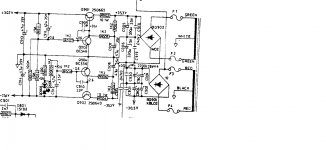
OK, so it has to come back to basic voltage checks. Concentrate on the negative rail only at this point.
If you know how it works you should quickly find the problem... I'm working from the diagram you posted earlier in the thread but all variations are similar in concept.
The PNP pass transistor Q902 should have negative 34 volts approximately on the collector.
That transistor is turned on via those two 1k2 resistors. That allows the output voltage to rise on the emitter. On their own this would allow the output to rise to the same as the collector volts.
Look at the Zener diode and series LED on the diagram. When the output voltage exceeds the Zener voltage (and the LED voltage) they conduct and turn on Q904.
Q904 now hold the base of Q902 at a stable voltage (Zener + LED voltage) and you get the regulated output at the emitter.
--------------------
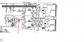
If the -34 volts is OK on the collector and yet the emitter volts is low then a quick and dirty test would be to lift R910 (also 1k2 make sure you are looking at the same diagram as me) which goes to the base of Q904.
The output voltage should now rise to an unregulated high value of around -32 volts.
If you try that then just power it on very briefly to see if the voltage appears.
That one test would tell us a lot.
Caution... there is a risk in doing this because the rails may rise to an unregulated high value equal to the input voltage to the regulators.
If you prefer you could try detailed voltage checks around that negative regulator to see if we can locate the problem that way.
We would need the voltage on all transistor lead outs (of Q902 and Q904) to begin with.
Also a leaky C910 (the 22pF) could cause this fault. If it is a small 'compressed disc' ceramic then it would be a type prone to going leaky.
im finding it hard to assertain which diagram is best representitive, they are all simlar but not the same so i think mine is the one attached as it has no impedence switch or a 6v supply direct from the transformer so im going to work my way through and check voltages and mark them up directly on the diagram.i did remove and test C910 with a heatsink and its almost spot on 22pf so thats ok.
your R910 is RS10 on my board, i guess its supposed to be a 5,(maybe should be 9) its all a bit all over the place.

Attachments
It is difficult without the correct diagrams
It will be interesting to see the actual voltages you have. Lets do that first if we can.
If that is inconclusive (but lets not do this just yet) then lifting one end of this resistor should bring up both negative and positive rails at the emitter of the two regulator transistors... but the rails will be high... assuming they do in fact come up of course.
And if they don't come up after doing that then we should have an easy fix
Voltages first though.
Attachments
OK, so it has to come back to basic voltage checks. Concentrate on the negative rail only at this point.
If you know how it works you should quickly find the problem... I'm working from the diagram you posted earlier in the thread but all variations are similar in concept.
The PNP pass transistor Q902 should have negative 34 volts approximately on the collector.
That transistor is turned on via those two 1k2 resistors. That allows the output voltage to rise on the emitter. On their own this would allow the output to rise to the same as the collector volts.
Look at the Zener diode and series LED on the diagram. When the output voltage exceeds the Zener voltage (and the LED voltage) they conduct and turn on Q904.
Q904 now hold the base of Q902 at a stable voltage (Zener + LED voltage) and you get the regulated output at the emitter.
--------------------
If the -34 volts is OK on the collector and yet the emitter volts is low then a quick and dirty test would be to lift R910 (also 1k2 make sure you are looking at the same diagram as me) which goes to the base of Q904.
The output voltage should now rise to an unregulated high value of around -32 volts.
If you try that then just power it on very briefly to see if the voltage appears.
That one test would tell us a lot.
Caution... there is a risk in doing this because the rails may rise to an unregulated high value equal to the input voltage to the regulators.
If you prefer you could try detailed voltage checks around that negative regulator to see if we can locate the problem that way.
We would need the voltage on all transistor lead outs (of Q902 and Q904) to begin with.
Also a leaky C910 (the 22pF) could cause this fault. If it is a small 'compressed disc' ceramic then it would be a type prone to going leaky.
im finding it hard to assertain which diagram is best representitive, they are all simlar but not the same so i think mine is the one attached as it has no impedence switch or a 6v supply direct from the transformer so im going to work my way through and check voltages and mark them up directly on the diagram.i did remove and test C910 with a heatsink and its almost spot on 22pf so thats ok.
your R910 is RS10 on my board, i guess its supposed to be a 5,(maybe should be 9) its all a bit all over the place.
OK, so it has to come back to basic voltage checks. Concentrate on the negative rail only at this point.
If you know how it works you should quickly find the problem... I'm working from the diagram you posted earlier in the thread but all variations are similar in concept.
The PNP pass transistor Q902 should have negative 34 volts approximately on the collector.
That transistor is turned on via those two 1k2 resistors. That allows the output voltage to rise on the emitter. On their own this would allow the output to rise to the same as the collector volts.
Look at the Zener diode and series LED on the diagram. When the output voltage exceeds the Zener voltage (and the LED voltage) they conduct and turn on Q904.
Q904 now hold the base of Q902 at a stable voltage (Zener + LED voltage) and you get the regulated output at the emitter.
--------------------
If the -34 volts is OK on the collector and yet the emitter volts is low then a quick and dirty test would be to lift R910 (also 1k2 make sure you are looking at the same diagram as me) which goes to the base of Q904.
The output voltage should now rise to an unregulated high value of around -32 volts.
If you try that then just power it on very briefly to see if the voltage appears.
That one test would tell us a lot.
Caution... there is a risk in doing this because the rails may rise to an unregulated high value equal to the input voltage to the regulators.
If you prefer you could try detailed voltage checks around that negative regulator to see if we can locate the problem that way.
We would need the voltage on all transistor lead outs (of Q902 and Q904) to begin with.
Also a leaky C910 (the 22pF) could cause this fault. If it is a small 'compressed disc' ceramic then it would be a type prone to going leaky.
ive had to give up for now as i am even more confused, and starting to think its a bit of a chop shop job, with a mix of different versions of this model amp.
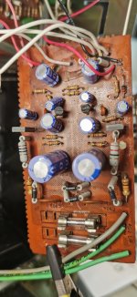
One thing that is confusing me is evry time i go to check something it appears to be in a different place to the drawing.Am i right in saying the 4 no diodes in my drawing represent the bridge diode.
on your drawing it shows the bridge as 4 seperate diodes layed out on the board instead of in a package, and this is how it is in my amp(see photo attached) but the wiring colours and config are as per the other drawing.
R no's differ and are in different positions
anyway my dining table doubles as my workshop and dinner becons
Attachments
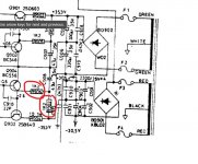
It looks like one of these two. If it is open then it would give the fault you have. You must check them with one end lifted to isolate it.
If it is open or high in value then that cap I have arrowed might be suspect as well.
If it is open or high in value then that cap I have arrowed might be suspect as well.
Attachments
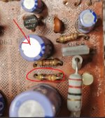
i did see this and removed it/tested it, and it was spot onI can see a burnt resistor just above the big blue cap on right hand side.
i do appreciate your help, as it is difficult when you are learning, but i will carry on!! and ill get back to you once ive checked the other bits out.It looks like one of these two. If it is open then it would give the fault you have. You must check them with one end lifted to isolate it.
If it is open or high in value then that cap I have arrowed might be suspect as well.
ive had to give up for now as i am even more confused, and starting to think its a bit of a chop shop job, with a mix of different versions of this model amp.
One thing that is confusing me is evry time i go to check something it appears to be in a different place to the drawing.
@poundy - you're not going crazy - the confusion is down to the poorly, if at all, documented changes the amp underwent in its early life. The good news is - since you have the separate power supply pcb, it has to be an original 3020 model, so the schematic you posted in your very first post is as correct as you'll find. My apologies if my previous post created any confusion - now you've posted a photo, it's clear which model it is.
There are still differences between what's in the manual, and what's in the amp, but not many - at least not in the 2 examples of the identical model I have just behind me. I'll pull the info I kept for those 2 and see what's there.
In the mean time, stick with it - it's worth it.
i do appreciate your help, as it is difficult when you are learning, but i will carry on!! and ill get back to you once ive checked the other bits out.
OK
and if you are unsure on anything then just ask.your R910 is RS10 on my board, i guess its supposed to be a 5,(maybe should be 9) its all a bit all over the place.
Re your guess re S,5, or 9, some of the legend on the board may have been worn away.
I am confident your RS10 is R109 a carbon film type which should be 0.25W 100R in value.
There is no RS10 in the parts list, in this all 10R resistors are 1W rated metal film types which you can identify from differences in appearance. None has an RS prefix.
All you need to do is to measure the resistance of R109 alias RS10 in circuit with the power turned off to see if this is good or bad.
PS that would be R912 in the first schematic you posted.
Last edited:
@poundy - you're not going crazy - the confusion is down to the poorly, if at all, documented changes the amp underwent in its early life. The good news is - since you have the separate power supply pcb, it has to be an original 3020 model, so the schematic you posted in your very first post is as correct as you'll find. My apologies if my previous post created any confusion - now you've posted a photo, it's clear which model it is.
There are still differences between what's in the manual, and what's in the amp, but not many - at least not in the 2 examples of the identical model I have just behind me. I'll pull the info I kept for those 2 and see what's there.
In the mean time, stick with it - it's worth it.
cheers for that.if there is one thing i never do, and that is give up.
i did see this and removed it/tested it, and it was spot on
There have been some arbitrary changes by increasing the resistor watt ratings. One of these is a 22 Ohm resistor mounted on spacers to the right.
According to the schematic attached to post 1 this should be 27 Ohms and 1W which should have been adequate.
You cannot guarantee the noise performance of a resistor which has signs of burning.
I've worked on 2 of the exact same model as 'poundy' seems to have - both of them had 10R 1W raised resistors for R903, and 22R 1W raised resistors for R904, all with what looked to be factory soldering, so I think that was a factory change. All the other resistors in the PS section were as per the schematic in Post #1
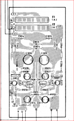
All of the caps on the PS pcb were also as per the schematic, except, they both also had 2 additional electrolytics, marked as C915 & C916 which are not on the schematic, but were original factory fitted. The 'extra' C915 & C916 are both 10uF / 35V, and they appear in poundy's pcb photo as well - the 2 smaller ecaps just above Q903 & Q904 in the photo.
(to add to the confusion - there are also 2X 2200uF / 35V filter caps marked as C915 & C916 in the schematic & service manual - so yes, NAD did use the same numbers twice, in the same amp).
i did see this and removed it/tested it, and it was spot on
Unfortunately we have been working from different versions of the circuit and one of the two resistor measurements Mooly was looking for has been missed.
That is R902 which is R908 in the version you posted at the outset. R906 the burnt resistor connects to C908 as shown on the pcb which is of interest .
It would be interesting to know what Q902 collector voltage is, and what the voltage at the junction of R902 and R908 is.
It is hard to see from images whether Q904 is a BC559 or not. The measurements on the leads are practically zero and it has a max of 30V which could be exeeded under fault conditions such as you have now.
That was replaced in later versions by BC546 which has a higher max voltage so replacing a BC559 with this makes good sense.
I am attaching images of the pcb as per the service manual and inverted to match the photo you posted.
Attachments
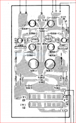
As R906 is burned looking and per post 14 C of Q904 is 0.056 v I would suspect C908 is shorted. the 47 uf series R906 with no label in the schematic, but on the negative side which has the problems. As Q904 is on the negative side I suspect the readings of post 14 are reversed by Q number.
Honestly, all these ecaps need replaced at this age. I don't buy them one at a time, the cap is $.35 and the freight is $9. I buy every e-cap in the amp, then I replace them 1 or 2 at a time then test voltage power on to make sure I didn't make the situation worse with a bad solder joint. BTW I buy caps rated >3000 hours service life so I don't have to do this again every 8 years as I had to in my ST70 with TV store grade caps.
Honestly, all these ecaps need replaced at this age. I don't buy them one at a time, the cap is $.35 and the freight is $9. I buy every e-cap in the amp, then I replace them 1 or 2 at a time then test voltage power on to make sure I didn't make the situation worse with a bad solder joint. BTW I buy caps rated >3000 hours service life so I don't have to do this again every 8 years as I had to in my ST70 with TV store grade caps.
- Home
- Amplifiers
- Solid State
- NAD 3020 series 20 power issues