I am currently working on an old series 20 amp, which i brought as a project to learn on realy as it didnt work.
the issue i have is that i cannot get any power beyond Q901 and Q909.
I have the correct voltage up to the collectors in each case (hope i got this right (NPN) but nothing beyond it,(appox 1.6v on the base and emmiters) so i guess the transistors are not turned on.
I have checked all the other local components and they are all good, so i am a bit stuck.
im trying not to ask questions and learn myself,but i have to admit to some defeat sometimes and ask for help
i also have no 6v supply to the LED board.
on this amp the 6v supply is not direct from the transformer but from the main board.
all power sources are good from the transformer
the other thing i dont understand is on the diagram it refers to a -25.6v on one side of the circuit but +29v on the other.Maybe you could explain for me.
many thanks for any help you can give.
paul.
Attachments
All 4 transistors are suspect. Remove each one in turn and do a diode test.
How to Test a Transistor & Diode >> Electronics Notes.
How to Test a Transistor & Diode >> Electronics Notes.
At face value that doesn't compute ")
1.6 volts (so you mean (plus 1.6 volts) would fully turn off Q904 and should allow the negative rail to rise to its maximum unregulated voltage (same as the collector volts).
If it was negative 1.6 then that would suggest Q904 was defective.
The negative rail is the one that defines all the operating points. Q902 and 904 are both PNP.
Are you sure you measured the voltages actually on the collector of Q902? If R904 was open you would get a fault like you have.
i also have no 6v supply to the LED board.
on this amp the 6v supply is not direct from the transformer but from the main board. paul.
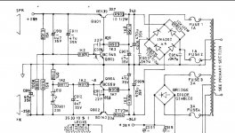
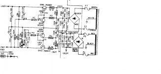
There are several schematics for the various versions of the NAD 3020, so it can be important to identify which is appropriate to your amp - from your earlier comment, I think you'll find this version is more likely correct (hifiengine.com has most of them). The differences are often small, but it can avoid confusion if you're discussing measurements & specific part numbers during troubleshooting.
Anyway, hope it helps.
Alan


If you get stuck then post the voltages you measure at all the transistor lead-outs.
Also... and going for easy stuff and easy checks... make sure R 906 and R908 are OK. Check them with one end of each lifted.
now i am confused.those resistors are shown at(1k2) 1.2k? on your diagram, and mine (attached) but the ones fitted are are 10.2k and are numbered R906 and R902
so same resistors in postions, but numbered differently,but wrong values
Attachments
If you get stuck then post the voltages you measure at all the transistor lead-outs.
Also... and going for easy stuff and easy checks... make sure R 906 and R908 are OK. Check them with one end of each lifted.
Q902
base -0.055vdc
collector -37.83vdc
emmiter 0.097vdc
Q904
base 0.0vdc
collector 0.056vdc
emmiter 0.0vdc
cheers ,paul.
If you get stuck then post the voltages you measure at all the transistor lead-outs.
Also... and going for easy stuff and easy checks... make sure R 906 and R908 are OK. Check them with one end of each lifted.
R906 and R908 are both 1.176k/1.174 so close enough to 1.2k +/- 5%
OK, so it has to come back to basic voltage checks. Concentrate on the negative rail only at this point.
If you know how it works you should quickly find the problem... I'm working from the diagram you posted earlier in the thread but all variations are similar in concept.
The PNP pass transistor Q902 should have negative 34 volts approximately on the collector.
That transistor is turned on via those two 1k2 resistors. That allows the output voltage to rise on the emitter. On their own this would allow the output to rise to the same as the collector volts.
Look at the Zener diode and series LED on the diagram. When the output voltage exceeds the Zener voltage (and the LED voltage) they conduct and turn on Q904.
Q904 now hold the base of Q902 at a stable voltage (Zener + LED voltage) and you get the regulated output at the emitter.
--------------------
If the -34 volts is OK on the collector and yet the emitter volts is low then a quick and dirty test would be to lift R910 (also 1k2 make sure you are looking at the same diagram as me) which goes to the base of Q904.
The output voltage should now rise to an unregulated high value of around -32 volts.
If you try that then just power it on very briefly to see if the voltage appears.
That one test would tell us a lot.
Caution... there is a risk in doing this because the rails may rise to an unregulated high value equal to the input voltage to the regulators.
If you prefer you could try detailed voltage checks around that negative regulator to see if we can locate the problem that way.
We would need the voltage on all transistor lead outs (of Q902 and Q904) to begin with.
Also a leaky C910 (the 22pF) could cause this fault. If it is a small 'compressed disc' ceramic then it would be a type prone to going leaky.
OK, so it has to come back to basic voltage checks. Concentrate on the negative rail only at this point.
If you know how it works you should quickly find the problem... I'm working from the diagram you posted earlier in the thread but all variations are similar in concept.
The PNP pass transistor Q902 should have negative 34 volts approximately on the collector.
That transistor is turned on via those two 1k2 resistors. That allows the output voltage to rise on the emitter. On their own this would allow the output to rise to the same as the collector volts.
Look at the Zener diode and series LED on the diagram. When the output voltage exceeds the Zener voltage (and the LED voltage) they conduct and turn on Q904.
Q904 now hold the base of Q902 at a stable voltage (Zener + LED voltage) and you get the regulated output at the emitter.
--------------------
If the -34 volts is OK on the collector and yet the emitter volts is low then a quick and dirty test would be to lift R910 (also 1k2 make sure you are looking at the same diagram as me) which goes to the base of Q904.
The output voltage should now rise to an unregulated high value of around -32 volts.
If you try that then just power it on very briefly to see if the voltage appears.
That one test would tell us a lot.
Caution... there is a risk in doing this because the rails may rise to an unregulated high value equal to the input voltage to the regulators.
If you prefer you could try detailed voltage checks around that negative regulator to see if we can locate the problem that way.
We would need the voltage on all transistor lead outs (of Q902 and Q904) to begin with.
Also a leaky C910 (the 22pF) could cause this fault. If it is a small 'compressed disc' ceramic then it would be a type prone to going leaky.
ok thanks for that, ill try this tomorrow and let you know how i get on.
 sounds like a plan.
- Status
- This old topic is closed. If you want to reopen this topic, contact a moderator using the "Report Post" button.
- Home
- Amplifiers
- Solid State
- NAD 3020 series 20 power issues