There are two sets of caps in parallel there and so you end up with the equivalent of a single 4400uF cap.
Remember caps in parallel add, the opposite of resistors in parallel.
(Caps in series are calculated the same as you would resistors in parallel)
Those 2200uF caps are the main reservoir caps and they smooth the rectified voltage from the bridge to give smooth DC.
Remember caps in parallel add, the opposite of resistors in parallel.
(Caps in series are calculated the same as you would resistors in parallel)
Those 2200uF caps are the main reservoir caps and they smooth the rectified voltage from the bridge to give smooth DC.
And just to clarify... the centre wire is ground and so it is the upper pair in parallel and the lower pair in parallel.
That centre ground or zero volt line splits the circuit in half. The top part generates the positive rail and the lower part the negative.
The upper and lower caps are not considered to be in series because they are used independently, separated by that ground connection.
That centre ground or zero volt line splits the circuit in half. The top part generates the positive rail and the lower part the negative.
The upper and lower caps are not considered to be in series because they are used independently, separated by that ground connection.

In some schematics for simplification there are blocks representing various sub-circuits - one could say there are two in your image and you would depict these in a flow chart in parallel. If that is all you are thinking then OK.
At a more detailed level, in your image R911 and C911 are in parallel (connected together at both ends). These are in series with R912 because these are connected only at one end. These are also in series with R907 for the same reason.
At a more detailed level, in your image R911 and C911 are in parallel (connected together at both ends). These are in series with R912 because these are connected only at one end. These are also in series with R907 for the same reason.
so in the attached,(if it were installed as such), anything in blue would be in parallel and in red in series?
its just this is what i am learning at the moment(going back on) and this is how i would understand it.
I think we might need to go back to basics for you to understand all this 🙂
We normally say something is in parallel when that something is placed across another component or another part of a sub circuit.
So we could add another cap in parallel (by placing it across) any other cap. The values would add as I mentioned earlier.
We can add something 'in series' which usually means a connection is cut or a component removed and something else added in-line with that break or component.
It is as mjona says 🙂
C910 is 'in parallel' with the Base Collector junction of Q904.
R903 is 'in series' with the Collector feed of Q901.
R911 and C911 are in parallel.
so R913 is also in series with these
R913 is in parallel with R912. So we would look at the circuit and say these two resistors form a single 13043 ohm resistor.
Try and work that value out yourself 🙂 A 100k and 15k in parallel.
We can they say that those resistors (or think of a single resistor of 13043 ohm) are in series with each other and placed between the positive and negative rails.
@poundy
If you need help the formula is 1/Rtotal=1/R913+1/912 =1/100k+1/15k.
The denominator becomes 15k times 100k =1500k. The numerator is the 15k+100k =115k.
You have to invert this to get the result where the numerator becomes 1500k and the denominator 115k. By simple division you get 13.043k
If there are more than two resistors in parallel add another 1/value to the equation.
so all back together, re capped and it sounds great, one thing tho, realy strange,when i tested its terminal outputs without the speakers connected, the power led's work fine, but once the speakers are connected and a load is applied, they dont come on, almost like the LED board had a power drain on it? any ideas?
the AMP works perfectly in all modes and outputs other than that issue.
the AMP works perfectly in all modes and outputs other than that issue.
It sounds a bit strange but if you can post a circuit diagram showing the LED in question we should hopefully be able to figure it out 🙂
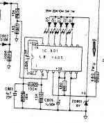
here is the diagram
the 2 main caps,tested are new and are ok
the zener diode was tested and is ok
i pulled the leg out of each resistor and they are ok
the only thing i havent tested is the small ceramiic cap C804 across the IC,i didnt want to risk damaging it as it is pretty small.
i could pull it and try a heat sink attached, but only if you think i have to.
i meant to add there is 30v going into R813 and 6v the other side
Attachments
Last edited:
Are you playing music quite loudly ? you may be surprised how little power you're actually using. My 3020's rarely light more than the first (1W) LED, and even that's often only on a particularly loud 'peak' in the music.
Alan
Alan
OK 🙂 I was thinking of a single LED on/off indicator.
Are you leaving the volume control set at the same position when you connect/disconnect the speakers?
I can't think of any reason why connecting a load would cause these not to work. If the supply is correct (and you have measured the 6 volts) then the only other check is to make sure the audio input is reaching the chip correctly.
so when the speakers are plugged in i have tried it from 0-to 80% and not one of the diodes lights
when the speaker cables are removed they light up gradualy as they would normaly do gradulaly as the pot goes from 0-100%
this is with the CD player running in both cases
when the speaker cables are removed they light up gradualy as they would normaly do gradulaly as the pot goes from 0-100%
this is with the CD player running in both cases
Last edited:
and another strange thing is when the speakers are disconnected, and i turn the volume up full, i can hear music playing somewhere within the amp.I though i was going mad, but i actualy can.Imagine a low cost transistor radio at very low volume, very tinny, this is what it sounds like, not loud at all, but just noticible at full volume
I wouldn't waste time pulling & measuring the disk cap. They usually only fail when subjected to overvoltage.
Way too much looking, not nearly enough measuring. Put a q-ball or pamona grabber on + of C911, what are the voltages with speaker detached & attached. Same measurement on negative of C912, speakers attached & detached. I don't think I've seen you report measurement of the +28.9 minus 25.6 voltages yet.
Continuing the fundamentals, what are voltages on + of C915 under both condition? Same test on minus of C916. If those voltages are collapsing with speaker attached would cause problems.
Last edited:
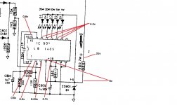
so this is what i have speakers disconnected and connected
weird though as the voltage is the same on the LEDS but they are not lit when speakers connected, and i can def hear music from the amp with the speakers disconnected
could it be a grounding issue?
weird though as the voltage is the same on the LEDS but they are not lit when speakers connected, and i can def hear music from the amp with the speakers disconnected
could it be a grounding issue?
Attachments
Last edited:
well ive done a bit of research indianajo, and it appears you are proberbly right.if you turn it up past about 70% the first light comes on, and apparently this is perfectly normal, so i guess problem over
i would still like to know however if there is a ghost in my machine lol as i can hear music when no speakers are connected 😱
i would still like to know however if there is a ghost in my machine lol as i can hear music when no speakers are connected 😱
Maximum watts on speaker before clipping proves the repair is successful. What is impedance of speaker? Z=(4/3)*R of speaker. P=(V^2)/Z P equals rating of amp, you have repaired it. Volts have to be read by an oscilloscope, Analog vom, or doorstop useless RMS capable DVM (up to 7 khz only). Analog VOM with 20 vac scale was $25 at Rural King farm store last month. Oscilloscope, Vav is approximately .7 Vpp.
Internal sound can come from inductors as the one in series with the speaker. Less common, wound caps can make noise. Usually cheap poorly constructed ones. Cheap TV's used to be full of caps made of wound up tin foil & paper, wrapped in cellophane glued together. Real garbage. NAD is not a premium brand amp.
You can detect which component is making the noise by sticking a rubber tube in your ear & waving the other end around over the components while the noise occurs. Fish tank tube or windshield wiper vacuum tube. NOT a metal tip stethoscope, no metal near a power on amp. Quicky mechanic's stethoscope.
Last edited:
It is normal to hear some components produce audible sounds... it used to puzzle me many years ago as I couldn't see an obvious mechanism by which it could occur. Power transistors and their contact with the heatsink seems to be one source I have noted in the past.
As to the LED's... disconnect the speakers and play music so that just the 1 watt LED flickers. Now connect the speakers without altering anything else and play the same part of the music again. The LED's should be lit as before.
As to the LED's... disconnect the speakers and play music so that just the 1 watt LED flickers. Now connect the speakers without altering anything else and play the same part of the music again. The LED's should be lit as before.
- Home
- Amplifiers
- Solid State
- NAD 3020 series 20 power issues