well so far ive changed 50% of them this morning on the main board and none have been below value, all higher by between 15% and 20%
Its funny the more you look, the more you see,and how poor some of the work is,especialy on the priinted side, although to be fair some of this could have been past poor workmanship i guess.
Its funny the more you look, the more you see,and how poor some of the work is,especialy on the priinted side, although to be fair some of this could have been past poor workmanship i guess.
To be fair the measured value tells you little about the cap 'goodness' beyond the obvious... its value. Often caps deteriorate by developing higher and higher E.S.R. (equivalent series resistance) which means a new cap might be like a 47uF in series with say 0.1 ohm). After a few years that value become 0.5 ohm, then 1 ohm, then 10 ohm and so on. The cap looses 'goodness'.
Its a little like measuring a 1.5 or 9 volt battery. They often read OK voltage wise but they can not deliver any current... similar type of thing, the internal resistance has increased.
For your 47uF to have caused the rail/s to disappear mean it must have been very leaky and so it removed (shorted to ground) the bias current needed to turn the regulator on.
The measurement we call ESR has to be done using an AC test signal and so needs a special meter.
Measuring DC resistance on a meter (and the polarity of the meter leads is important when testing electrolytics) can sometimes show a very leaky cap.
The best way to get a feel for that is to measure some new caps. The larger the cap and the worse the leakage will appear to be.
A quick test in the case of your circuit would have been to measure the volt drop across each of those two 1k2 resistors. Because they are in series then volt drop should be identical across each one. That hold true no matter what other fault there might have been.
So if the cap was removing the bias current you would find R902 would have much more voltage across it than the other one.
so nothing much gained by testing resistance of the cap out of circuit with a MM then
i did try a few, all of the same value (47uf) 2 of them held steady at about 26m ohm but the other one was 6 m ohm, them eventualy went O/L
i did try a few, all of the same value (47uf) 2 of them held steady at about 26m ohm but the other one was 6 m ohm, them eventualy went O/L
It doesn't really tell you much unless the fault is a near short on the cap. In theory all caps should read open circuit when tested at DC which is how a DVM works.
I've found that caps that are high ESR have 10-20% higher capacitance than rated. My ESR meter was stolen, I'm not buying another one. Waste of $110. Where ESR meter would really save time on PC mainboards, and those have dozens of caps in parallel, so you can't tell which cap is making it not boot up until you take it out. If you take it out, may as well replace it IMHO.
Andy G the moderator of organ forum says his "engineer" (UK) takes e-caps out, checks them, puts them back. "Has never found a bad one." I don't post on that forum anymore, AndyG finds my obsession with 30 year old rubber sealed e-caps unhelpful. The 1980 Allen organ that in 2018 was producing 2 watts out of two S100 amps, produced 100 W per amp after I re-e-capped them. The Allen service tech on the forum told AndyG that "Allens never need new electrolytic capacitors".
My Hammond H182 that was producing 3 watts on the 2 treble channels and 7 on the bass channel, is now producing 13 w on the treble channels and 35 w on the bass channel. Also the string bass (sustain), and "percussion" (attack envelope) functions now work, which didn't when I bought it.
I've just purchased a Peavey M-2600 75 w/ch amp which is putting out 2 w/ch. We'll see what $30 of e-caps does for it.
Last edited:
It doesn't really tell you much unless the fault is a near short on the cap. In theory all caps should read open circuit when tested at DC which is how a DVM works.
so with the values i got just with the few i tried what would that indicate?
It indicates the DC resistance at the moment you actually do the measurement but it doesn't really tell us much.
Your meter works by applying a test voltage between the probes and seeing what current flows. From that the the reading on the meter is scaled to be in ohms.
So even the polarity of the meter leads will make a difference on the 'resistance' of a capacitor because a if it happens to reverse bias it then the cap will pass more current and give a lower ohms reading.
Temperature will affect the result and so will the working voltage of the cap along with just differences between different makes. So while any 47uF cap might reasonably be expected to read 47uF when tested, the leakage may vary by several orders of magnitude between type and yet all are OK.
A large cap will give a reading that seems to increase over time and that is because the meter test current is so low that the cap takes time to charge and so gives an inaccurate reading.
A very large cap would have a normal leakage current that would be in excess of the test current a meter can supply and so you would never get a meaningful result.
OK 🙂 I know its a lot to take in but as you progress it will start making more sense.
If we looked with an oscilloscope at the ripple voltage across a big power supply cap then we could see on the scope that a small change in the ESR (the caps goodness) would make quite a difference to the measured ripple.
If we looked with an oscilloscope at the ripple voltage across a big power supply cap then we could see on the scope that a small change in the ESR (the caps goodness) would make quite a difference to the measured ripple.
To be fair the measured value tells you little about the cap 'goodness' beyond the obvious... its value. Often caps deteriorate by developing higher and higher E.S.R. (equivalent series resistance) which means a new cap might be like a 47uF in series with say 0.1 ohm). After a few years that value become 0.5 ohm, then 1 ohm, then 10 ohm and so on. The cap looses 'goodness'.
Its a little like measuring a 1.5 or 9 volt battery. They often read OK voltage wise but they can not deliver any current... similar type of thing, the internal resistance has increased.
For your 47uF to have caused the rail/s to disappear mean it must have been very leaky and so it removed (shorted to ground) the bias current needed to turn the regulator on.
According to the schematic the earth point for the centre tap of the winding for the regulator section is not local.
If there is resistance in the centre tap earth path perhaps due to bad wiring or a dry joint what happens to these 47uF capacitors with suppression capacitors C903 and C904 sitting between the secondaries and connecting to the earth line.
Those caps are just across the secondaries for suppression of the bridge.
Even if there were an open circuit in the grounding somewhere, the 1k2 resistors would limit any current flow in the 47uF to about 25 to 30 milliamps peak at a guess. That would be a worst case scenario assuming the reservoir caps were out of circuit as well.
Maybe I'm not following what you mean 🙂
Even if there were an open circuit in the grounding somewhere, the 1k2 resistors would limit any current flow in the 47uF to about 25 to 30 milliamps peak at a guess. That would be a worst case scenario assuming the reservoir caps were out of circuit as well.
Maybe I'm not following what you mean 🙂
there is a grounding tap on this boardAccording to the schematic the earth point for the centre tap of the winding for the regulator section is not local.
If there is resistance in the centre tap earth path perhaps due to bad wiring or a dry joint what happens to these 47uF capacitors with suppression capacitors C903 and C904 sitting between the secondaries and connecting to the earth line.
Those caps are just across the secondaries for suppression of the bridge.
Even if there were an open circuit in the grounding somewhere, the 1k2 resistors would limit any current flow in the 47uF to about 25 to 30 milliamps peak at a guess. That would be a worst case scenario assuming the reservoir caps were out of circuit as well.
Maybe I'm not following what you mean 🙂
This is a long shot but having looked at the pcb the order of earth precedence on the regulator looks OK for a remote earth point. We don't know where other earth systems unite and how.
After 40 or more years one could not guarantee the ripple handling capacity of main regulator capacitors rated at 35V and supporting a rail voltage of much the same level - more if the mains supply is towards the high end of tolerances.
There is an enlarged area of copper on the pcb for cross flow between the bottom ends for rectified charging currents to settle ( more would have been better) but whatever residue flows tees off through a branch to the bottom ends of C907 and C908. For no apparent reason these have become leaky.
The emitters of the BC549 and BC559 (high gain) are in close proximity to these capacitors - contrary to conventional thinking on current flow electrical charges flow from emitter to collector. There is potential via this route for some spurious residue on the earth line to enter and have deleterious impact on the regulator performance. That would not be expected when the amplifier was new but not that would have to be considered given the age now.
In the beginning earth route would have been better in the opposite direction in my view.
Anyway in the service manual R903 is a 0.5W 10R resistor where in the subject amplifier this is a 22R one that looks to be about 2W in rating. This raises the question is there a stability issue in that.
The main capacitors here are either 470uF in one version or 330uF which appears to be from a more recent version which I see as the one to go for.
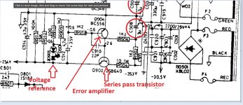
The regulator is really the whole of that circuit but you could break it down and say it consists of a top half and bottom half. The bottom half is the negative regulator and the top the positive regulator.
The negative one is important in this configuration because the output of the negative side is used to provide a reference for the positive one.
It is called a regulator because the output voltage remains constant even if the input voltage varies and also if the load current varies.
The negative one is important in this configuration because the output of the negative side is used to provide a reference for the positive one.
It is called a regulator because the output voltage remains constant even if the input voltage varies and also if the load current varies.
Attachments

Last edited:
- Home
- Amplifiers
- Solid State
- NAD 3020 series 20 power issues