Ice cubes and fire symbols ....
And run all this , soft-start, temp , V/I , DC with (below).
Bias could get ice/smiles/ and flames. Just seen
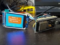
the GUI development apps for ESP32 w/ ST7735 color display.
Watch your cap banks charge with a battery icon (soft start phase).
Fancy , fancy.
OS
And run all this , soft-start, temp , V/I , DC with (below).
Bias could get ice/smiles/ and flames. Just seen
the GUI development apps for ESP32 w/ ST7735 color display.
Watch your cap banks charge with a battery icon (soft start phase).
Fancy , fancy.
OS
Attachments
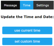
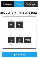
For anyone new to ESP8266 not not new to programming. Here is an example of a small clock I made for my desk at work. The library versions indicated much be used. Im not using the new json parser.
Just an example of handeling webpages to be served by the esp itself.
This project creates its own Access point and does not connect direct to internet. I did not spend much time on making the webpages it serves to be pretty. But they are nicely viewable on PC and mobile.
Instead the user logs into the wifi hotspot provided by the esp.
Attachments


I was using something like this on mine ...
https://www.semicon.sanken-ele.co.jp...1186_ds_en.pdf
Along with 3 pair of the big MT-200's.
1.5k - R110/100R - R111
No issues.
My similar HK680 uses 2sa1837/2SC4793 , but with only 2 pair of
120W sankens.
1.5k/220R as predriver/driver Re's.
No issues here , either.
OS
I know this is out of sync with the current topic, but I'm trying to get an understanding of my options for the output devices. Based on post #317, I'm intending to use Sanken 3264/1295's, as they're sitting in a box looking for a good home. Wolverine looks like a great fit. My novice view is that I really wouldn't have to make any other component changes, with the exception of biasing needs. Any thoughts/help on this would be greatly appreciated.
Reading IR commands while running a LCD is problematic, both time consuming operations so they don't play well together.
If we stick to the ESP, you can just run separate tasks and assign appropriate priorities. I‘m running 8 tasks in my hay feed controller and it works quite well
")
Perhaps what you want to consider is to use the existing bias controller and tap of two connections to a separate bias controller that would then fine tune the bias to correct for ambient and/or allow switching say between class A, AAB and AB. Very easy to write some code in C++ to cal the bias controller and set all this stuff up. You can make it fail safe.
This leaves those that want a stock Wolverine to build as is, and those that want extra features to add the bias board.
This leaves those that want a stock Wolverine to build as is, and those that want extra features to add the bias board.
Last edited:
That is how it is , Bonsai.
Don't populate OPTO 1 , primitive it will stay.
You would not want to have any true (wired) external bias control , as the Vbe is
output and +/- 2V. As a mains like but high Z signal , keep it tightly confined
to the Vbe "cage".
The opto is just a precision fine tune of the existing main bias trimmer.
Luckily , default is still the trimmer. I set up my simulations with default
at 40mA , where the window of very low distortion begins at high power.
Sankens even do better AB @ 50mA , ON 70 - 80mA ... different silicon.
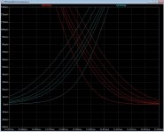
(below) is what range a 100K trimmer in series with a 47K would give
hooked to a 5V supply (though the OPTO). the bottom (40mA) step is what switching the
opto out of the circuit entirely would have.
I saw your EF3 Vbe , single device Vbe's are adequate for EF2's.
My oldest amp , Sansui EF3 .... set it high cold (80mA) , has negative Tc.
Ends up 40-50mA when hot. HK , 80mA .... 0C to 70C (+/- 3-4mA).
Drops that 3-4 from 40C-70C.
So , just a front panel control. 110mA limit , I noticed no issue running
5 of these same designs anywhere within this range.
Best to leave any automated (or refined) bias control to a micro. Just
toggling a few preset steps would be as easy as kids lighting up LED's
with a Arduino. ESP32 , seen a kid on his phone triggering leds over wi-fi.
OS
Don't populate OPTO 1 , primitive it will stay.
You would not want to have any true (wired) external bias control , as the Vbe is
output and +/- 2V. As a mains like but high Z signal , keep it tightly confined
to the Vbe "cage".
The opto is just a precision fine tune of the existing main bias trimmer.
Luckily , default is still the trimmer. I set up my simulations with default
at 40mA , where the window of very low distortion begins at high power.
Sankens even do better AB @ 50mA , ON 70 - 80mA ... different silicon.
(below) is what range a 100K trimmer in series with a 47K would give
hooked to a 5V supply (though the OPTO). the bottom (40mA) step is what switching the
opto out of the circuit entirely would have.
I saw your EF3 Vbe , single device Vbe's are adequate for EF2's.
My oldest amp , Sansui EF3 .... set it high cold (80mA) , has negative Tc.
Ends up 40-50mA when hot. HK , 80mA .... 0C to 70C (+/- 3-4mA).
Drops that 3-4 from 40C-70C.
So , just a front panel control. 110mA limit , I noticed no issue running
5 of these same designs anywhere within this range.
Best to leave any automated (or refined) bias control to a micro. Just
toggling a few preset steps would be as easy as kids lighting up LED's
with a Arduino. ESP32 , seen a kid on his phone triggering leds over wi-fi.
OS
Attachments
Last edited:
hi, at what point is the project? Thanks
Lol, I was wondering as well, what is the next step?
That's a good point. NJW's , 18mm - hole to lead.
We have 19mm from UMS holes to pcb holes.
It would take a lot of valuable real estate to relocate for MJL's , they need
22 -24mm. They did not think out UMS well. outer row should of been
25mm out instead of 20.
Looks like to-247 MOSFETS are 17-18mm , like the NJW's.
UMS was primarily for class A amps , and one package.
I'm not re-doing the board. Taps some holes 5mm out.
Edit - they will fit , if not for UMS ... made for Pass.
HFE classes for the rest .... BCxxx = "B" (546B/556B).
Those are the active devices.
Wolverine Q12/13 should be higher gain. CCS's and cascode , no matter.
Q1/2 , 5/6 also higher gain (BCxxx - B) ..or C.
Spooky is all cascodes , just Q1-4 and Q11,14 matter for higher gain (BC's).
OS
Last edited:
Wiil the version with OPC will be designed ?
Also is there any way that we can use TO-3 transistor in the output stage ? if so, what will be the modifications apart from PCB ?
Want to know those details as a beginner, if this question doesnt make any sense, kindly Ignore.
Also is there any way that we can use TO-3 transistor in the output stage ? if so, what will be the modifications apart from PCB ?
Want to know those details as a beginner, if this question doesnt make any sense, kindly Ignore.
Hi OS,
I don’t know if transistors like MJL4291/MJL4302 and MJL4281/MJL4302 will fit on the output board, if that’s what people want to use.
I thought that the MJL4302/4281AG were the preferred Output devices? That's what I was planning on using... Or am I missing something? I thought the output spacing would be the same as the Badger?

I thought that the MJL4302/4281AG were the preferred Output devices? That's what I was planning on using... Or am I missing something? I thought the output spacing would be the same as the Badger?
We are discussing the UMS mounting hole. If you drill and tap holes on a heatsink, this should not be a problem.
Stuart and I are checking creepage and lead space dimensions - will report back soon.
- Home
- Amplifiers
- Solid State
- DIYA store "Wolverine" (Son of Badger) .... suggestions ??