I think at first to assemble and listen without a case, if I like the sound to buy a chassis with radiators. In addition, of course, it is necessary to add capacitors, but without fanaticism, since practice has shown above 39000 microfarads in the shoulder gives little increase (example Dartzeel). But 22000 4 pieces also cost a lot . Hobbies require sacrifice.
Unfortunately, while at work, perhaps I will be at home only after January 15th. From work and ordering components for the A60 project. There are no days off.Welcome to the club my dear friend,
You've made good decisions regarding the component selection. I have also, among others, used ISC output transistors and they are very fine. I have measured them carefully with curve tracer and I must say that I do not see the difference between ISC and "Toshiba" transistors. Both are Chinese: Toshiba China and ISC China too. Correct me if I'm wrong but there was Chinese spaceship on Mars so I don't question their capability to produce quality transistors too.
Meanwhile, I've made quite a few experimental work on this amplifier. Just let me know what you need.
And, you're right, this may prove to be an expensive adventure, especially heat sinks, capacitors and chasis if you want to do everything right. This costs.
I wish you a pleasant week end.
But wait before you make decision to buy. A "smaller" A60 with "just" 3 output pairs per channel has a great deal of power and has identical structure. Also, there is no difference in sound. It requires less "sacrifice" especially in heat sinks, capacitors, output devices and chassis. That means less edpenditure in items that dominate the overall cost. Ask yourself do you really need huge amplifier with "pointless" 8 output pairs to achieve just 20W of pure A class power. It is true that you can have much more of fine power but just AB power. Think before you spend more.I think at first to assemble and listen without a case, if I like the sound to buy a chassis with radiators. In addition, of course, it is necessary to add capacitors, but without fanaticism, since practice has shown above 39000 microfarads in the shoulder gives little increase (example Dartzeel). But 22000 4 pieces also cost a lot . Hobbies require sacrifice.
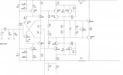
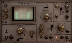
Hi Berlusconi, Parahod4, and that's it! He depicted the diagram as they say from nature. There may be bugs. Correct. The scheme is in Proteus, I post it in Jpeg. Who needs it in Proteus format, write your email. I would be glad if the diagram is useful to someone. I have not yet defeated the noise even on the breadboard, if you press your ear to the speaker, you can hear something similar to 50Hz. If you solder the IN-GND jumper, then there is no noise. If the cable is a meter long and all the conductors are short-circuited at the end to the ground, there is noise.. USB-Oscilloscope with Aliexpress did not help me (low sensitivity and ADC bit depth). I want to buy a device from the USSR (everything will be fine there with metrology, minus the age of the device).

Hi VMK2002,
I knew you would make a progress and you've done a great deal of progress indeed. You recall me to myself when I were of your age: incarnation of courage, determination, boldness, dedication to the task. You're a born winner. Never surrender.
Now, one advice regarding the purchase of oscilloscope. First gain some experience with the device you already have ( dont care it is almost a toy) and try Windows program Arta, it is a demo but you can use complete functionality, except for saving settings. You can do many serious things with it. All equipment you need is a good sound card. But carefully, you may burn it without adequate little device you may find here. I will show you later. I have just arived home and I'm exausted.
Then you may decide what is the right thing for you. Also even mid-range oscilloscopes arent useful for FFT analysis due to low data depth.
You have made a great schematics. I have made it too but without some details. I will publish it later on so you can compare them. I will do that too. I have also made a draft of LTSpice simulation. I also plan to publish it soon.
So, lets keep working
Zdravo Slavko,
Yes there are some missing data and perhaps some errors. I will verify everything and get back to you with even more data.
What I want is to help VMK2002 to complete his schematic, which is indeed clear and well organised. Then I would like to make a final draft of LTSpice simularion file and publish it so more experienced members may work with it and getback to uswith a working simulation file.
Could you please join our efforts? Any help is welcome indeed.
Regards
PS: R18 and R20 are both 33 Ohm, near the right edge of the scheme.
Last edited:
Good afternoon. I am slowly making my clone A-60, so there is little help from me. Replaced all transistors, 970/2240 for KSA / C 992/1845, 1145/2705 for KSA / C 1381/3503, driver MJE15032 / 33, output MJL1302 / 3281. And I decided to convert it to EF3. TTA / TTC004 pre-driver. But I haven't listened yet, now I'm making a power supply. When I launch it, I will share my impressions with you.
Attachments
Thanks Slavko,Good afternoon. I am slowly making my clone A-60, so there is little help from me. Replaced all transistors, 970/2240 for KSA / C 992/1845, 1145/2705 for KSA / C 1381/3503, driver MJE15032 / 33, output MJL1302 / 3281. And I decided to convert it to EF3. TTA / TTC004 pre-driver. But I haven't listened yet, now I'm making a power supply. When I launch it, I will share my impressions with you.
I did almost the same replacements except, I have used NJW at the output stage.
But, my measurements indicate that CDIL A970/C2240 aren't that bad at all. Therefore I plan to revert one of the boards back to CDIL transistors to make side-by-side comparisons. One board with ON Semi and the other board with CDIL transistors. It is interesting that CDIL parts were so easy to pair within 5% tollerance. Now I want to know how different devices influence signifficant performance parameters. It should be noted, however, that 992/1845 aren't equivalents of 970/2240, just the closest attainable devices. My curve tracer measurements indicate that the CDIL transistors could be the better choice. More linearity, closer hfe and better curve traces. There is a thread at this forum that indicates that CDIL A970 has low noise.
I have three pairs of boards which I have personally assembled so I can investigate the difference on the bench.
Lets keep in touch.
Thanks for your input - I appreciate that.
Regards
Over the weekend I will try to compare your version of the scheme and mine, I will make amendments. I already see different values of the input signal divider at the input. By the way, it seems to me that the transistors 2sa970/2sc2240 are excessively amplified, since I set the lowest volume control level on the preamplifier and already get a not quiet response in acoustics. Have you paid attention to such a moment on your motherboards? I associate this with the power supply of the amplifier from a 36V transformer. In my main amplifier Marantz PM80 MK2 SE, the power supply of the output transistors is +/- 24V in class A, and +/- 50V in class AB. Most likely +/- 50V is a lot for class A.
Hi VMK2002,
This oscilloscope looks surreal indeed, a big boy. It must be fun to use such a rare piece of equipment.
Meanwhile, I have installed Proteus on my PC. I have bare boards so I can verify the schematics but I think you're 100% accurate, mine is faulty and incomplete.
Please, publish your Proteus file, I would like to use it and simulate.
This turns into very interesting business.
Thanks for your contribution
You're right but If you have 60V capacitors, you're on the safe side...... Have you paid attention to such a moment on your motherboards? I associate this with the power supply of the amplifier from a 36V transformer. In my main amplifier Marantz PM80 MK2 SE, the power supply of the output transistors is +/- 24V in class A, and +/- 50V in class AB. Most likely +/- 50V is a lot for class A.
You've mentioned previously slight noise when you have ears in very close vicinity of your speakers. You can eliminate that with more capacitance attached to the power supply section.
I have tested with good capacitance multiplier. In that case the amplifier is completely death silent. Also, measurements indicate very low noise level.
Additional question; do you like the sound? I assume you use quality source and good recordings while testing the sound?
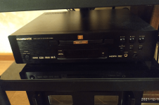
The weak links are the BRZNIFI preamplifier and the DAC from them on the ES9018 SABRE. The collection contains branded CDs, including XRCD, K2HD. The direction is mainly Fusion. Alas, the popularity of high-quality recordings is falling and in my city there is only one store that sells branded discs. For electronic formats, I do not yet have equipment comparable in quality to hardware. Yes, and it is more pleasant for me to listen to discs, since you can hold them in your hands. By the way, I have equipment for copying and burning such discs for my personal collection and a supply of blank discs from Taiyo Yuden.
A proposito, quasi dimenticavo la cosa più importante... Link al progetto in formato Proteus:
https://disk.yandex.ru/d/_VXqksHZYBaF4g
https://disk.yandex.ru/d/_VXqksHZYBaF4g
Thanks VMK2002,
But what I really want to know is: do you like the sound of your A60+?
Before you're absolutely sure everything is okay use lower transformer voltage and lower bias to prevent damage. Watch temperatures. Be sure that D669 is properly attached to the heat sink.
But what I really want to know is: do you like the sound of your A60+?
Before you're absolutely sure everything is okay use lower transformer voltage and lower bias to prevent damage. Watch temperatures. Be sure that D669 is properly attached to the heat sink.
What can I say. I have Marantz. For the time being, everything was fine with me, until acoustics appeared with a speaker with a diameter of 31 cm and a suspension that dries out from time to time, and which needs to periodically restore its elasticity by impregnation (Diatone DS Z77). The power supply of the old amplifier was no longer enough. This A60 + is not bad, it is more energy-efficient. But there are nuances. The A60 amplifier (or complete transformers from China) are sensitive to the phasing of the supply voltage. Humming until you flip the power connector. Noise is also heard in pauses near the subwoofer. There are problems (or while there are problems) on the test board with MJL 4281/4302 transistors, namely the oscillogram of a square wave signal. There are a lot of bursts on the rise and fall edges of rectangular pulses. Or else the board is not with completely replaced fakes from China, or other resistor values for these transistors are needed (they should be 5200/1943). Today I will receive my oscilloscope and will look for problems. Again the 2240/970 transistors should be shipping soon. You can't get sound quickly for cheap, you need to think and finish. This is our hobby, isn't it?
- Home
- Amplifiers
- Solid State
- A60(+) Amplifier. Build this?