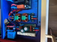
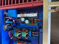
On the right and on the left, where large white resistors and capacitors (diodes are not visible), this is a LAMM filter from a constant in the network, with it, together with a power filter, in series, also each to its own channel.🙂

I didn't understand the question. The surge protector with coils is factory-made, but without a separate grounding, since I do not have it, the filter circuit from the constant in the network is the same that I posted.🙄
Does this mean that you have good sound coming from your speakers, without hum, buzz and noise?... I have a problem like this. Transformers hum, and you can hear it if you are near the amplifier case (I'm not talking about sound in acoustics)...
If so, you have succeeded. Congratulations!
Then you have easier problem to deal with. I am sure Paroxod has good solution for your problem. But wait - Erlend is right too. By adding more capacitance you may significantly improve the sound. I have tried with externally adding extra 4X22.000uF/63V per channel. Bass and treble are even much better. Bass is indeed powerful. But good capacitance costs. I went a moderate way with 4X22.000uF/63V Fischer+Tauche GMB223063500, per channel.
But for now, if I may advice you, first solve the problem with transformer, then adjust the bias and in the end add some extra capacitance.
Good luck
Last edited:
Hi Berlusconi! I am very glad for your answers. Yes, I beat the noise in one of the channels simply by using a quality shielded wire from a HBM strain gauge sensor. Moreover, it has 2 twisted cores, and I soldered one of them to the "-" RCA-connector and to "-" INPUT on the amplifier board. Only with such a connection, the noise became much less. The other channel is still noisy, but I associate this with a poor-quality transformer (I am already expecting the delivery of a new one, and I hope that the surge protector will solve some of the problems). If this does not help, I will look at the oscilloscope power diagrams. And it is possible to replace the capacitors and be sure to install 2μF film capacitors in parallel to the electrolytic capacitors. Now comes the most important thing. The Chinese assured me that he had adjusted the quiescent currents of the output transistors before shipping. I want to check it out. The amplifier boards have contact pads labeled TEST and potentiometers for adjustment. Tell me the method for setting the quiescent current of transistors, preferably with details.
They adjust bias to safe value, which is fair. This prevents possible thermal runaway and consequently destruction of the board. You can run your amplifier safely at the pre adjusted bias. 20 mV across the test point is OK. Even at this value the amplifier sounds great. The increase of bias may improve the sound but at cost of increased temperature and risk. With large heat sink ( 0.3 W/C) I was able to run it at the maximum value, 60 mV. But it is rather hot. Optimal is up to 30mV. But be careful, your Chinese chasis has smaller heat sinks. For now wait with bias before you get clear sound withour noise.
Try this: bridge the input with 1K resistor: one leg into signal connection and other leg into gnd. Connection. This may sighificantly reduce the hum. Connect grounds of the input RCA connectors and keep them as close as possible.
Try this: bridge the input with 1K resistor: one leg into signal connection and other leg into gnd. Connection. This may sighificantly reduce the hum. Connect grounds of the input RCA connectors and keep them as close as possible.
Erlend Sæterdal, hello! I want to ask this question. Before using a line filter with DC cut-off function, did you have problems in the form of rumbling transformers? By the way, the filter with Aliexpress, to which I gave a link, helped me in solving this problem. I just had to replace the 2200uF capacitors with 10000uF. Moreover, this filter works only with one position of the plug in the outlet. Does your filter work in any position of the plug in the outlet? Berlusconi until he took your advice. I want to clarify, according to your advice, as I understand it, will 1kOhm resistors of minimum power be suitable? (I don't hear the noise of the torus now, but I can still hear it in 50Hz acoustics, I will fight). It is also very interesting which preamps you use. So far I bought this one:
https://aliexpress.ru/item/40009314...43.1544783349.1626670217-552916735.1579052756
But I want to replace over time with something more interesting. In search of. Advice from passionate people would be very helpful!
PS: My filter:
https://aliexpress.ru/item/40002481...tem_id=4000248160625&sku_id=10000001005213527
Last edited:
... I will fight...


That's right: never surrender.
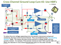
Now, regarding resistors: that 1K resistor may be any low wattage. Currents are very low there. In addition to that you may add an additional resistor with value between 4R7 and 10R to serve as hum breaking resistor (HBR).
Let me explain this with a diagram below which is taken from a presentation at hifisonix.com.
In the middle of the scheme there is a point denoted with letter B. Your 1K resistor is located at the vertical line connecting point B with input of the amplifier. Now follow the line going from point B towards the HBR resistor. Simply connect the HBR resistor between the point B and GND at the terminal for speakers. Ground of the speaker is connected to a star connection on the board. This should reduce hum further to the minimum.
50Hz sound is related to the quality of reservoir capacitors. I use here 4X22.000 uF/63V quality capacitors. The type of capacitors I have mentioned few posts previously. If needed you can connect the amplifier to additional power supply, but there is no enough room for this in your chassis.
I'm glad to see your remarkable progress. Never surrender.😎
Attachments
vmk2002 Connect the transformers to the network in antiphase with respect to each other, farther into the screen, or farther from each other. In the previous position, one above the other (they stand close) also helped me. The background and buzzing disappeared.🙂
Paroxod and vmk2002
Caution: I have clicked on the link from vmk2002 post and I was re-directed to the Russian Aliexpress site. Now, they have hi-jacked my browser and I can not access the "normal" Aliexpress site. Even when I type explicitly the .com extension they re-direct me to the .ru site.
This indicates that Aliexpress intentionally redirect Russians and these who have accessed the Russisn site. This smells fishy, there is a foul game behind: they do this to rip you off easier by keeping you out from the real site.
Hi, don't worry, this is fixable. You can fix your browser settings. Confidentiality and security.
Erlend Sæterdal, hello! I want to ask this question. Before using a line filter with DC cut-off function, did you have problems in the form of rumbling transformers? By the way, the filter with Aliexpress, to which I gave a link, helped me in solving this problem. I just had to replace the 2200uF capacitors with 10000uF. Moreover, this filter works only with one position of the plug in the outlet. Does your filter work in any position of the plug in the outlet? Berlusconi until he took your advice. I want to clarify, according to your advice, as I understand it, will 1kOhm resistors of minimum power be suitable? (I don't hear the noise of the torus now, but I can still hear it in 50Hz acoustics, I will fight). It is also very interesting which preamps you use. So far I bought this one:
https://aliexpress.ru/item/40009314...43.1544783349.1626670217-552916735.1579052756
But I want to replace over time with something more interesting. In search of. Advice from passionate people would be very helpful!
PS: My filter:
https://aliexpress.ru/item/40002481...tem_id=4000248160625&sku_id=10000001005213527
Sometimes my transformers was noisy yes. But my main reason for implementing DC blockers is better sound. More detailed treble and more punchy bass.
Hi Berlusconi! Finally, I got the necessary set of transistors and capacitors (SAMWHA HC). Now it's time to set the quiescent current of the output transistors. How to do it right? How long do you need to withstand after switching on, do you need to short-circuit the amplifier inputs to the GND? What signal should be at the TEST points, whether it is necessary to disconnect the amplifier outputs from the acoustics. Thanks in advance for your answers. And yes, do you have any new "patients" in hi-fi technology?
Hi vmk2002,
First, I am very glad to hear from you after quite some time, a good news. I am glad you've gone this far.
Before setting the bias you should make sure that your output transistors are properly fixed to the heat sink and that you have used adequate amount of thermal compound on the both sides of mica/ceramic isolation tabs.
Second, but very important: the d669 transistor must be fixed to the the same heat sink as your output transistors. This prevents thermal runaway. This works in this manner: as the temperature of power transistors increase, current through them would increase too. The d669 transistor compensates this trend and it will reduce the bias current accordingly. This is a feedback control loop that prevents thermal runaway which could otherwise lead to excessive current and finally to self-destruction of transistors.
Be careful: Chinese deliver boards with d669 transistor mounted above the board. It should be underneath the board as the power transistors. In this way the d669 will sense the increase of temperature and counter thermal increase of current through the power transistors.
You should be aware, that as in any feedback control loop there is certain delay: transistors first warm-up, then temperature of heat sink starts to increase and then the d669 transistor will "sense" that change.
Therefore you must increase bias value slowly, about in steps of 1/4 of turn, not faster. Then measure voltage between these two holes denoted with "TEST". Measure in mV range with minimum 3 significant digits (005). At the beginning that value should be low.
Before you start adjustments connect the signal input to the signal ground. Readings are valid just in the absence of signal. Do not connect amplifier to speakers. Use instead 8 ohm dummy load, at least 50W. If you don't have such a load, connect it to some cheap speakers. Do not connect any expensive speakers now. The amplifier has own upc1237 speaker protection but you never know.
Turning the potentiometer counter-clockwise increases the bias. Increase the value slowly until you reach the value of 20mV. Stop now and observe the temperature. Heat sinks will warm-up slowly. The rate of increase depends on the size of your heat sinks. Small heat sink warms-up faster.
Do not adjust bias any further for now. Leave amplifier turned on for an hour and observe the voltage reading and temperature of the heat sinks. To heat-up the power transistors you may connect signal to the input. Preferably 1KHz sinusoidal.
Before continuing, connect input and input ground to avoid erroneous readings.
Now you may proceed increasing you bias in steps of 5 mV every 30 minutes.
I have stopped this when temperature of the output transistors has stabilized at 45-50 C and 35mV. You may go further but it may be too risky without obvious advantage.
Currently, I work on a smaller version of A60, with 3 pairs of output transistors, with completely original parts. Only boards is from China, nothing else. I have assembled them as separate mono-blocks with separate transformers. In this case there is no ground loop - grounds are connected to input at just one point. This guarantees total absence of ground-loop problems.
I also have another new A60+ board which I plan to first completely de-solder and use exclusively original parts. Not just transistors - everything, including relays and electrical terminals.
I'll keep you informed.
Kind regards 🙂
PS: Where do you purchase components? I hope not from Aliexpress. I don't have any prejudices, but I have (I hope) healthy brains and I know that transistors from that source are almost certainly (99.99999%+) not originals, modestly speaking. In my builds I have now original ON Semi MJL and NJW devices, besides all other original components. Just one fake among them will ruin all your efforts. It would be a pity, as we know that transistors constitute just a fraction of overall costs. All we want is just top quality. Don't forget that. We don't want yet another Maos' Rollex.😉
Last edited:
Hi Berlusconi. Thanks for the detailed explanation of the method for setting the quiescent current of transistors. Apparently my voltage from the transformers is higher than yours. Namely 36VAC. Therefore, we managed to get only 12mV, then the radiators begin to warm up significantly. Tell me, what is the alternating voltage from the transformers you get on the boards?
Hi Berlusconi, how are you?
I read the entire post because I am very interested in putting the A60.
Can you tell me what the sound and spec differences are between the A60 with 3 pairs of transistors and the A60+?
Would it be an increase in power in the A60+?
Thanks in advance.
I read the entire post because I am very interested in putting the A60.
Can you tell me what the sound and spec differences are between the A60 with 3 pairs of transistors and the A60+?
Would it be an increase in power in the A60+?
Thanks in advance.
Thanks Claredes,
I'm fine though exausted after a hard working week.
I'm sory for late response. It is late here, Friday evening and I will provide you answers tomorrow in the morning.
Berlusconi
I'm fine though exausted after a hard working week.
I'm sory for late response. It is late here, Friday evening and I will provide you answers tomorrow in the morning.
Berlusconi
Acchuphase Clone Favorit Amp.
Overall my preferred amp and I have many. Mono amps up to 700 W 8 ohm.
Overall my preferred amp and I have many. Mono amps up to 700 W 8 ohm.
- Home
- Amplifiers
- Solid State
- A60(+) Amplifier. Build this?