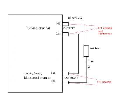
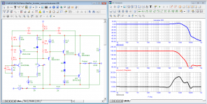
Petr, try something like in picture..Tested chanel with shorted input. You can try single tone, step, square, sweep... signal for driving channel, what you like.. This is real test of back EMF influence . And compare in audioband amp with and without global NFB ")
picture with courtesy of PMA
picture with courtesy of PMA
Last edited:
He doing his usual trick - running away and changing the subject completely. The back-EMF - while of course a real phenomenon - has nothing to do with the ramblings on esoteric distortions and other misunderstandings.
He will not answer you but come back with yet another strawman.
Jan
He will not answer you but come back with yet another strawman.
Jan
Petr, try something like in picture..Tested chanel with shorted input. You can try single tone, step, square, sweep... signal for driving channel, what you like.. This is real test of back EMF influence . And compare in audioband amp with and without global NFB
picture with courtesy of PMA
That's what I've been doing. It's very effective.
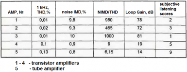
I have already cited the correlation of different testing methods with subjective listening ratings. Here is the test result for 5 amplifiers. Published by A. Syrytso in the magazine "Radio" 1999-04
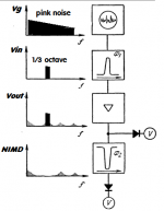
this is much more informative than a multi-tone test, since the frequencies in the selected spectrum are not fixed. Such a test is as close as possible to a real musical signal, therefore, there are speed distortions associated with changes in the frequencies of the spectral components and their amplitudes.
BV, this is how the output impedance is measured, a common practice
Attachments
Last edited:
Everything asociated with real musical signal is safe in audio band..since the frequencies in the selected spectrum are not fixed. Such a test is as close as possible to a real musical signal, therefore, there are speed distortions associated with changes in the frequencies
We have a bit more knowledges now than in 1999... Wake upin the magazine "Radio" 1999-04
Last edited:
BV, you assume that he understands his own posts. If you look over the history here, it is clear he doesn't. He just searches the internet to find things he likes, not understanding the meaning or context, and posts that. That is why he always runs away from any questions and comes back with a different topic. You can't maintain an intelligent discussion if you don't even understand your own posts, and that is what we see here.
I have tried to help him make progress towards better understanding but he's not interested, very unfortunate.
I think we should leave this thread to Petr and wish him well.
Jan
I have tried to help him make progress towards better understanding but he's not interested, very unfortunate.
I think we should leave this thread to Petr and wish him well.
Jan
Jan, BV - it's really hopeless to discuss anything with you if you can't grasp what Graham explained to you almost 20 years ago
Graham explained his position in simple, accessible language. He repeatedly explained what linear distortions are, even cited excerpts from radio technical reference books, where linear distortions mean only a fixed change in the signal amplitude and phase and there are no additional harmonic components !!! And this is possible only in a steady state. During the period of transient processes, the shape of any signal is highly distorted and enriched with additional harmonics, which has nothing to do with linear distortion.
As for the FCD, Graham wrote:
Bob Cordell Interview: Negative Feedback
«If a class-AB amplifier tests out better with a suddenly starting 10 kHz sine (no matter whether this might be thought unrealistic) then it is also likely to be capable of establishing a more stable stereo image of an instrument like a cymball or violin due to either or both amplifiers being less disturbed by back-EMF. »
Bob Cordell Interview: Negative Feedback
«Better 'first cycle' results do actually follow through into reproduction as more stable imagery, especially minor presences which are not disturbed by more powerful instrumental transients as loudspeaker drive is substantially increased. Everyone knows that you must run several cycles to obtain a 'best' thd figure, but hey, that is not what happens in the music world !!! You can have a good thd figure yet still have a compromised transient performance, but you cannot have a good first cycle performance without the thd being even better to start with (unless there is an asymmetry to circuit activity which makes one first cycle polarity better than opposite). And yes bandwidth does come into this, but amplifiers must be stable and so often it is the application of stabilising components that affects the untested (suddenly starting / transient) first cycle accuracy.»
Tired of fighting obscurantism, Graham wrote:
Bob Cordell Interview: Negative Feedback
«Maybe someday others will use their simulators more innovatively, possibly with real time analysis. However I cannot, and I am not in any position to do more, so I will bow out and go back to enjoying the trustable reproduction outcome of my own findings. »
I gave a link to an article about Bob Carver's controversy about bringing his relatively simple and cheap amplifier to the level of an expensive prestigious amplifier. I think that only the Haffler test, which he owned and understood perfectly, helped him to make such a refinement, as well as a deep understanding of how the amplifier can be adjusted so that the signal propagation delay time becomes less than 10 ns (-70 dB vector distortion)
Last edited:
Your ideological comrade clear enough to describe your understanding of the problem with the words: "Yes music sources are bandwidth limited, but they still start suddenly, esp percussion, thus I fail to see your reasoning here."
Maybe you will be able to understand what failed him - limiting the bandwidth leads to limiting the rate of rise is a fact that the physics of the process. And based on his statements, you subscribe to his words, thus showing the insufficiency of your theoretical training.
Carver reduced the difference between the amplifiers to -70 dB, and not the vector error of a single amplifier. I'll draw an analogy - you have $ 200 in your pocket, and I have 130, but the difference between us is $ 70. And the difference does not tell us anything about the absolute values of the amounts in our pockets.
Last edited:
At one popular forum, a competition was announced for the best amplifier correction in order to squeeze out the maximum feedback depth and, accordingly, get the minimum distortion in the entire sound band.
More than ten participants took part in the competition. Most used the theoretical training provided by the university and used Douglas Self's favorite low first pole correction. Only two contributors got creative with the simulation results which I have already presented in the thread above.
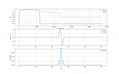
In addition, I will give only the result of the Hafler test (for skeptics).
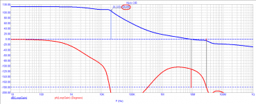
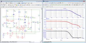
To remind what was discussed, I attach a diagram. Buikvarev remained faithful to his approaches (which, by the way, completely coincide with the opinion of Ciryl Hammer).
Draw your own conclusions. For completeness, you can pick up the branch in which I gave THD measurements
More than ten participants took part in the competition. Most used the theoretical training provided by the university and used Douglas Self's favorite low first pole correction. Only two contributors got creative with the simulation results which I have already presented in the thread above.
In addition, I will give only the result of the Hafler test (for skeptics).
To remind what was discussed, I attach a diagram. Buikvarev remained faithful to his approaches (which, by the way, completely coincide with the opinion of Ciryl Hammer).
Draw your own conclusions. For completeness, you can pick up the branch in which I gave THD measurements
Attachments
-
 12_Nick_test-Hafler.png37.2 KB · Views: 70
 -
 08_Nick_concurs_Loop-Gain.png24.5 KB · Views: 77
 -
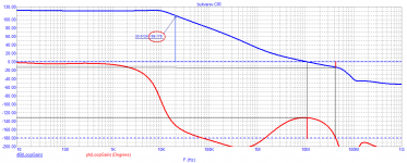
 07_Nick_concurs_Bode.png74.3 KB · Views: 96
 -
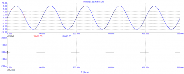 06_Bukvarev_test-Hafler.png19.4 KB · Views: 93
 -
 01_bukvarev_concurs_Bode.png70.8 KB · Views: 177
 -
 02_bukvarev_concurs_Loop-Gain.png24.8 KB · Views: 192
 -
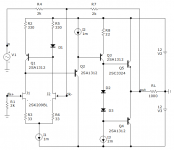 SCH.png26.6 KB · Views: 181
Last edited:
Show the Hafler test scheme in the form in which you implement it in the simulator. Otherwise, your results cannot be checked and this is another throw-in. You have avoided inconvenient questions in my post 638, but I do not insist, everything is clear to everyone.
The given examples of correction were due to the specified conditions of the competition - obtaining the maximum loop gain at 10 kHz. The task was not to get a workable sample, so the results should be considered taking into account these limitations. And the correction requirement for a single gain with closed feedback allows you to get some additional visual bonuses. Bypassing the cascades along the correction circuits at high frequencies allows you to show an impressive zero group delay.
The given examples of correction were due to the specified conditions of the competition - obtaining the maximum loop gain at 10 kHz. The task was not to get a workable sample, so the results should be considered taking into account these limitations. And the correction requirement for a single gain with closed feedback allows you to get some additional visual bonuses. Bypassing the cascades along the correction circuits at high frequencies allows you to show an impressive zero group delay.
fagos, you obviously do not have enough understanding, just understanding. And it's not even your lack of education. Some graduated from several universities, but they remained fools. Knowledge must be able to be applied in practice. And for this it is not enough to know, it is also necessary to understand. I gave the Hafler circuit for non-inverting amplifiers several times above. An inverting amplifier requires an inverter to feed the amplifier under test (I used an ideal inverter). And since the amplifier is with unity gain, there is no need for an attenuator either. I hope I explained it clearly.
I taught you a lot at first, but now I see your gratitude in the many posts that you post here.
I taught you a lot at first, but now I see your gratitude in the many posts that you post here.
Looking at your recent postings calling people stupid fools, my posting of a while ago concerning a misunderstoog genius syndrome still seems valid, you haven’t made any progress in structured presenting and discussing a thesis.
Instead I still see the same continuing graphical incontinency telling little or nothing at all, although just a few theories might possibly bring something, but are just put forward as facts instead of starting a proper investigation/discussion with members on this forum, leading to some form of conclusion.
I can assure there are lots of people on this forum quite a bit smarter and more experienced than you and me.
And if you don’t like the idea to discuss things structured and in depth, then what exactly are you doing here ?
Hans
Last edited:
An interesting statement from a person who argued with me and tried to prove that stability should be viewed by open loop gain.Continue in the same style."I have taught you a lot" - an incorrect statement. I was taught by reading books, independent work with pencil and paper, as well as constant analysis of the results obtained. But why are you now jumping so quickly from one model to another, escaping the dialogue with Jan Didden? The one who wants to prove his case and is sure of it does not do so. This is what those who do not have enough opportunities to understand what their opponent said and they hurry to change the topic of conversation.I taught you a lot at first, but now I see your gratitude in the many posts that you post here.
Of course, I understand that it is easier for you to reduce everything to emotions, calling everyone ungrateful and making everything look like you are a great guru, but this does not negate the fact that you need to prove your calculations. And gratitude has nothing to do with it at all, when a scientific dispute is being conducted in order to establish the truth, they try to show you your mistakes with all their might so that you do not waste time on the wrong path. If by gratitude you mean the need to remain silent, looking at frankly erroneous things, then this is not my style. And do not blame me for the lack of practice, first show your real measurements, not simulations.
I perfectly understand the Hafler test, but in order to repeat your simulation results, you need to do exactly the same as you do, in order to exclude the possibility of a difference. This is called the scientific approach, which they have been telling you about for so long. It implies the desire to exclude possible places of errors and discrepancies in advance. And I already made models with corrections of Bukvarev and Nick last night, I received graphs. If someone from those present in the topic wishes, I can upload the analysis files to Microcap 12 or any additional simulation results in graphical form.fagos, you obviously do not have enough understanding, just understanding. And it's not even your lack of education. Some graduated from several universities, but they remained fools. Knowledge must be able to be applied in practice. And for this it is not enough to know, it is also necessary to understand. I gave the Hafler circuit for non-inverting amplifiers several times above. An inverting amplifier requires an inverter to feed the amplifier under test (I used an ideal inverter). And since the amplifier is with unity gain, there is no need for an attenuator either. I hope I explained it clearly.
You have received input-output vector error graphs, but we are not listening to the input-output differential difference. And your references to Carver's experience do not work here, because there is a slightly different scheme of the experiment, as I wrote earlier, but you ignored it as always.
My position is very clear from the very beginning: the time propagation delay (tPD) is responsible for the sound quality in amplifiers with GNFB, all other things being equal.
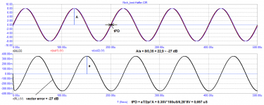
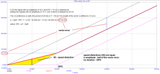
I fully and completely share Graham's position on the distortions of the first period (FCD). Basically, these are speed distortions that depend on tPD and are equal to:
in amplitude - half of the vector distortion;
by duration - 2 tPD
This is illustrated in the figure below and all the necessary calculations are shown. The area of the yellow triangle is the speed distortion that appears on audio signals, as well as on noise signals. Even in multi-tone tests, they practically do not appear, not to mention two-tone ones.
Starting from the second period, there are no more velocity distortions on the sinusoidal signal. As arguments, I showed this on numerous examples of both model analysis and the example of the experiment of Bob Carver, who took the level of vector distortion of -70 dB as a "zero test", which corresponds to tPD = 10 ns.
fagos, show me at least one post of opponents with arguments refuting my position, mostly a continuous flood. Or maybe you will refute my position? Or the position of non-NFB amp manufacturers such as Threshold, Rowland, Krell, Nelson Pass and many others who have abandoned overall negative feedback. This is fully consistent with the position of Cyril Hammer, which you "like" so much.
no wonder Hawksford paid so much attention to open-loop amplifiers
So the flag is in your hands ...
offtopic: When they boast that they have a measuring laboratory based on a sound card, it's funny to me. It's like bragging about a 50-year-old Chinese pointer voltmeter.
Attachments
Last edited:
offtopic: When they boast that they have a measuring laboratory based on a sound card, it's funny to me. It's like bragging about a 50-year-old Chinese pointer voltmeter.
Indeed, funny. That must be why Audio Precision sells APflex sound card interface measurement software for $ 3000.
My soundcard with REW can do measurements that your precious Hafler doesn't even see.
You're soooo clueless!
But you wouldn't know; you haven't done any of those measurements anyway. Armchair scientist.
Jan
Last edited:
- Home
- Amplifiers
- Solid State
- Musings on amp design... a thread split