Member
Joined 2009
Paid Member
To mitigate the risks, I would overcompensate the thermal compensation.
I would redesign the base spreaders as Vbe multipliers, this allows overcompensation if required.
It is even more overcompensated, but it will probably be needed in reality
So in this method, how/where these transistors should be mounted
to track temperature?
Would this work better than 4 extra Schottky diodes?
Hi Bigun,Ian, I have been interested in a power buffer and Nelson’s F4 meets my criteria. Can your square-law approach be implemented in such a simple open loop buffer topology ?
Good question. Square-law operation can almost halve the idle current without reducing the leaving-Class-A power (25W according to the manual).
Before you race off and pull out all the source resistors I would like to try and do a thermal simulation to see if it safe to go with square-law's..
A few questions:
Is your build the one on "prod_f4_man.pdf" p16? Or which?
What is the approximate thermal rating is your heatsink?
Do you know the spec of the thermal pads?
Is the TL431 on the heatsink mid mount? Or on top of a package?
The manual says 3x0.46A with 46V is 63.watts (mono) and no PS heat. Is that about right for your amps?
So in this method, how/where these transistors should be mounted to track temperature? Would this work better than 4 extra Schottky diodes?
Hi minek123,
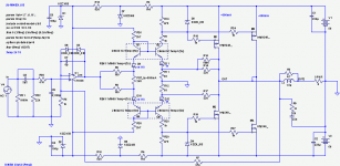
Since you mention Schottky diodes I assume you have seen the circuit attached in Post 18. For convenience of all I'll put it below:
My simulation shows two Schottky diodes give enough static thermal compensation for the 50V rails with two pair of HEXFETs.
I still need to do a dynamic thermal simulation to find a thermal rating suitable for a practical heatsink. Until this simulation is done we can't be know if this 50V amplifier is thermally stable (or not) without source resistors.
If all looks well I should do a 50V bench test with two pair of well matched N's and a pair of P's. But I don't know if I have such a pair on hand at the moment. I'll have a look soon. Then I can try different mounting spots for the Schottky diodes for you.
Attachments
Member
Joined 2009
Paid Member
Hi Bigun,
A few questions:
Is your build the one on "prod_f4_man.pdf" p16? Or which?
What is the approximate thermal rating is your heatsink?
Do you know the spec of the thermal pads?
Is the TL431 on the heatsink mid mount? Or on top of a package?
The manual says 3x0.46A with 46V is 63.watts (mono) and no PS heat. Is that about right for your amps?
I do not have a build in progress, but it is something I have been considering for awhile. I have the flexibility of buying new heatsink if I need to and may have to as most of my existing stock is sized for Class AB. These are implementation details, what is more interesting is what might be the preferred circuit design. The F4 has enough in the way of positive reviews to suggest further improvements may not warrant much in the way of additional cost / complexity but this thread certainly encourages some thinking in that direction. I have also wondered whether a BJT version would not be preferred due to higher gm = lower distortion but that would not be able to take advantage of a square law approach.
The F4 uses 3 pairs of output HEXFET’s.
The biassing with the TL431 is not the only way to skin that cat. The M2 and BA2 are proven alternatives from Nelson.
Last edited:
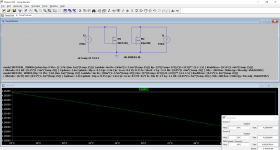
This first stage for a dynamic thermal simulation now working. Files attached. Circuit below and a plot. (Heatsink time constant accelerated from 1ks to 1 second).Hi All,
...I still need to do a dynamic thermal simulation to find a thermal rating suitable for a practical heatsink. Until this simulation is done we can't be know if this 50V amplifier is thermally stable (or not) without source resistors.
.
There are actually two pairs of IRFP240/9240 in parallel (using the 'm' area scaling factor). Idle current is as before 300mA per pair. The Schottky diodes sense the MOSFET case temperature and offsets the 25C diode voltage by -1mV/C. There are source resistors that are used if the simulation overheats and would need them. In the plots above the source resistors are disabled and you can see that it is stable both at startup (initial idle condition) and when running at high power for a while. When the signal stops you can see the diode voltage V(e1,X1) rises again but the idle currents I(Rs1) and I(Rs2) stay almost the same and at the same as the initial idle current at the start. if the heatsink rating is too high there is thermal runaway from the start by solving the steadystate operating point. If you change Rsa to more than 0.6 degC/W for two pair (eg enter as "1.2/prs") and it should crash on start with ridiculous Tj's and currents. That's as expected in real life. Then increase Rs to see if it can be made stable with source resistors.
In this simulation use Vtrim parameter to set the idle current. This is an offset voltage needed to make the thermal model start at the same as the standard model would at starting 25C. The Vtrim is not part of the build just a software tweak to get it to match the previous fixed temperature simulations.
The subcircuit is complicated and needs a tutorial paper to show how to use it and how it works. It was keantoken's idea and I helped develop it over the last 5 years; now updated to run with the new LT-XVII VDMOS model temp-cos. So far I have only run it on LT-IV but hopefully it should run as is on LT-XVII as well. So far I only have Exicon laterals and the IRFP240 in the attached thermal model file.
I see ngspice has a similar inbuild VDMOS model that can do this type of thermal simulation (without a subcircuit). I am still learning to use ngspice so I can't provide any thermal files for this circuit for ngspice at least for a while.
All the best with this simulation.
Attachments
Last edited:
>So in this method, how/where these transistors should be mounted to track temperature?
>Would this work better than 4 extra Schottky diodes?
I asked, because I wonder what are pros and cons of both solutions (Elvee's Vbe multipliers vs Schottkys).
Elvee's solution, if it works, seems simpler.
It does increase distortion slightly more than Schottkys..
>Would this work better than 4 extra Schottky diodes?
I asked, because I wonder what are pros and cons of both solutions (Elvee's Vbe multipliers vs Schottkys).
Elvee's solution, if it works, seems simpler.
It does increase distortion slightly more than Schottkys..
Last edited:
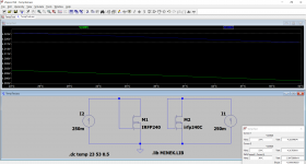
I have measured a real transistor, because the models looked unreliable.
The measurement confirms my suspicion: I swept the temp from 23°C to 53°C, using this test setup:
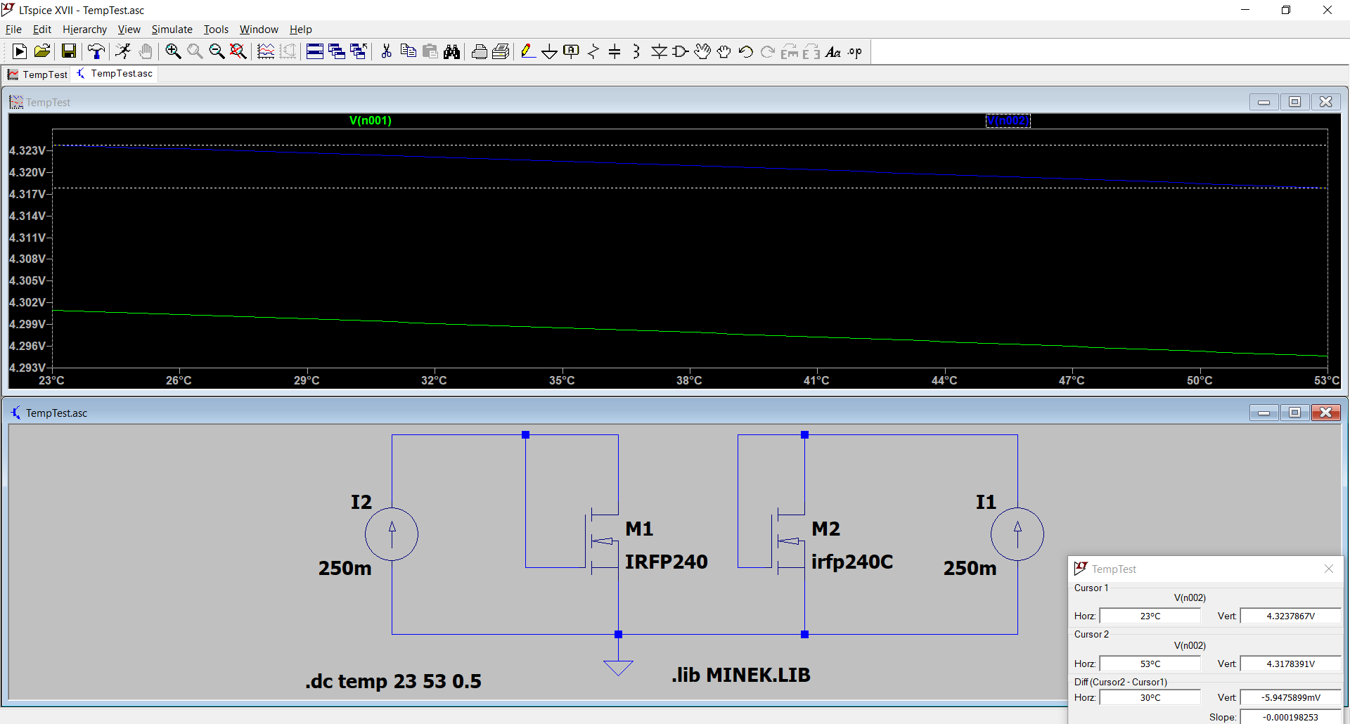
The sim for both models shows a variation of only 6mV, but in reality it was much higher: 115mV (from 3.920V to 3.805V).
That's an average tempco of -3.83mV/°C.
It is not possible to use a sim to determine the best strategy if the models are unable to reproduce this behaviour.
The measurement confirms my suspicion: I swept the temp from 23°C to 53°C, using this test setup:
The sim for both models shows a variation of only 6mV, but in reality it was much higher: 115mV (from 3.920V to 3.805V).
That's an average tempco of -3.83mV/°C.
It is not possible to use a sim to determine the best strategy if the models are unable to reproduce this behaviour.
Attachments
It is not possible to use a sim to determine the best strategy if the models are unable to reproduce this behaviour.
Elvee, please note that Ian is using different models - not the ones from my lib,
but models that he attached directly to the .asc file.
Not sure what is the difference, but I'm assuming Ian's models are better.
The models I used are different to Bob Cordell's and the inbuilt IRFP240 in LTspice. Neither of these two sources provide the required temperature effects on threshold voltage and Kp (transconductance) for these power MOSFET's.
My IRFP240 and IRFP9240 models are embedded in my sim files and include appropriate temp-cos, eg Post 5 here https://www.diyaudio.com/forums/attachments/solid-state/847501d1590462986-square-law-amp-hegglun_hexfets-35v-ih1-zip
Bordodynov now has all my latest VDMOS models and is integrating them into his library (his old version link here Installing and using LTspice IV (now including LTXVII). From beginner to advanced.). When he has posted the updated mosfet library I can post a note on this thread if you like.
BTW none of the standard.mos VDMOS models supplied by ADI in LTspice install currently have suitable temp-co parameters for our power MOSFETs. They are only correct at 25C. The inbuilt models all use the default which is Vtotc of -1mV/C and 1.5 for Bex. So we have to make our own versions by add the correct temp-co for Vto by adding 'Vtotc' parameter typically -6mV/C, and Kp by adding 'Bex' parameter typically 2.2 for 1st generation power MOSFET's like the IRFP240. These 2 parameters are only for LT-XVII since May 2019. For LT-IV you need to use curly bracket equations in the model. The LT-IV versions of all my VDMOS models will be made available by bodrodynov as a separate library file to the LT-XVII library file.
Hi jcarr,Hi Ian,
The "prod_f4_man.pdf" document that I have is 16 pages long, and the schematic is to be found on page 13.
FWIW, it appears as though a source resistor-less output stage that suits an F4 could also be made to work with an M2.

Hmmm, count me interested!")
Oops
, yes the F4 circuit is page 13, as your manual.The M2 needs source resistors for it's auto-bias loop, so you can't eliminate the source resistors! Possibly a supercap from source of Q1 to source of Q2 would give square laws above the f-3dB frequency (eg 15Hz for 2.5F). See here Emitter resistor in HexFet OPS
I purchased two 5F supercaps a few months back to test this idea but have been busy on another project.
Hi Bigun,I do not have a build in progress, but it is something I have been considering for awhile. I have the flexibility of buying new heatsink if I need to and may have to as most of my existing stock is sized for Class AB. These are implementation details, what is more interesting is what might be the preferred circuit design.
The F4 has enough in the way of positive reviews to suggest further improvements may not warrant much in the way of additional cost / complexity but this thread certainly encourages some thinking in that direction. I have also wondered whether a BJT version would not be preferred due to higher gm = lower distortion but that would not be able to take advantage of a square law approach.
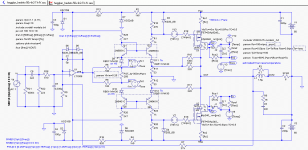
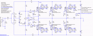
OK so to see what is possible the attached thermal simulation allows the source resistors to go to zero and the idle current reduced for square-law mode which is half the standard bias. The thermal simulation allows the heatsink temperature to be assessed as the heatsink size is changed. And whther the heatsink is too small to stop thermal runaway without source resistors.
This circuit doesn't have all the exact F4 parts but is close enough for now to simulate the thermal effects and likely distortion (including thermal memory distortion). I did not have the TL431 (adjustable zener) model so I have made my own using a BJT with a programmable temp-co. (for evaluation only not for a practical build).
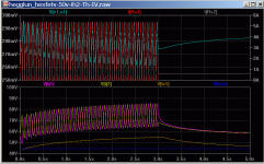
I found the capacitors across the bias generator needs to be reduced and series resistors added to get the simulation to work. The plot below is with 250mA per pair, then a burst at full output swing, then no signal to see watch the transient decay. The bias temp-co hsa been chosen so 1) thermal runaway is prevented, and 2) the transient is not over-compensated too much.
BTW the heatsink is 'Rsa' which is the portion for one device. The overall heatsink rating will be Rsa divided by the number of devices or Rsa/6 in this circuit. The attached sim is set for Rsa=6 which means the overall rating is 1C/W for the amp -- maybe a bit small heatsink since the temperature gets close to 80C after running at full output for a while -- but still it does not appear to go to infinity (thermal runaway) - it flattens off so is safe with no source resistors with this temp comp and small heastsink. Obviously a reality check is needed (bench test) to see if the simulation is realistic
.A quick check on THD with square-laws showed lower distortion than the manual. In driver stage also can be set for no source resistors for reduced distortion as well.
This is mainly as a demo so you can try variations using thermal modelling. BTW the ngspice site has a tutorial on thermal modelling ngspice tutorial for electro-thermal simulation
Attachments
Hello Ian.
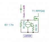
You are torturing yourself with complicated thermal stability , where as it is very simple. The LM334 is temperature dependent current generator . It's reference voltage drifts 0.23mv/°C. by this the current drifts in the 227ua÷R.
example, you have 470 ohm gate-source resistance and you want the voltage drifts by -3mv/°C. Than the LM334 must increase it's current by 3mv÷470=6.38ua/°C than the R=227÷6.38=35.5 ohms . The extra current the LM334 will draw is about 1.7 ma.
All you need is to install the LM 334 +R on a small pcb along the 470 ohms and the protect zener and screw it upon the MOSFET where the LM334 is inserted on either half circle groove , and the two terminals of the circuit are soldered on gate and source. By this you get a single element. To try it out , you need to bias the transistor in the air with a power supply and heat the transistor with a soldering iron on it' drain pin and fine adjust to keep the current constant while heating up.
Attachments
Last edited:
My IRFP240 and IRFP9240 models are embedded in my sim files and include appropriate temp-cos, eg Post 5 here https://www.diyaudio.com/forums/attachments/solid-state/847501d1590462986-square-law-amp-hegglun_hexfets-35v-ih1-zip[/URL
LTspice gave a warning, but the result is even worse: the total variation is now 4.8mV
Attachments
Oops - updated circuits attached
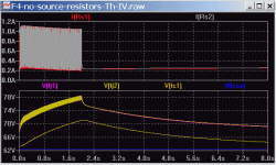
Oops, I found a few bugs. Sorry. The attached "F4-no-source-resistors" file has corrections. Delete the earlier file if you downloaded it. The Thermal model file is updated (with new name).
Changed: sense point for the bias sensor to the heatsink (was on the MOSFET case). It is still stable with no source resistance and 1 degC/W heatsink. Output still 25W into 8 ohms, bias 250mA per pair (750mA total), about the half original bias and heat, thanks to square-laws.
Yet to add the bootstrap parts and the TL431 (and a thermistor?). Anyone interested?
Hi Bigun,
OK so to see what is possible the attached thermal simulation allows the source resistors to go to zero and the idle current reduced for square-law mode which is half the standard bias...
Oops, I found a few bugs
. Sorry. The attached "F4-no-source-resistors" file has corrections. Delete the earlier file if you downloaded it. The Thermal model file is updated (with new name).Changed: sense point for the bias sensor to the heatsink (was on the MOSFET case). It is still stable with no source resistance and 1 degC/W heatsink. Output still 25W into 8 ohms, bias 250mA per pair (750mA total), about the half original bias and heat, thanks to square-laws.
Yet to add the bootstrap parts and the TL431 (and a thermistor?). Anyone interested?
Attachments
Last edited:
Oops - updated circuits attached
Well, a bug was in the models file, so this simulation was affected too.
Attached is the corrected "hegglun_hexfets-50v-ih2a-Th" file with the corrected model file. Delete the earlier file if you downloaded it. Sorry for that error.
Changed: sense point for the bias sensor to the heatsink (was on the MOSFET case). It is still stable with no source resistance and a 0.5 degC/W heatsink. Idle current is 300mA per pair (600mA total).
Hi All,This first stage for a dynamic thermal simulation now working...
Well, a bug was in the models file, so this simulation was affected too
.Attached is the corrected "hegglun_hexfets-50v-ih2a-Th" file with the corrected model file. Delete the earlier file if you downloaded it. Sorry for that error.
Changed: sense point for the bias sensor to the heatsink (was on the MOSFET case). It is still stable with no source resistance and a 0.5 degC/W heatsink. Idle current is 300mA per pair (600mA total).
Attachments
Member
Joined 2009
Paid Member
Hi Bigun,
Yes, there is another issue to check with unmatched like polarity MOSFETs current sharing and hence thermal stability for a possible runaway failure. The simulation I have done assumes perfect matching of like polarity MOSFET's.
To do a simulation for mismatch you can add a voltage source of say 5mV in one MOSFET gate. Also try increasing the source resistance of one MOSFET. Monitor the sensitivity (% change in say Id to % change in Vg or Rs) -- and that's if it is thermally stable with an imbalance added.
Nelson Pass mentions in his 2019 BAF talk some commercial amps have been made with no source resistors (or no emitter resistors) but Nelson said they don't have a reputation for reliability (or similar words).
The general assumption is that they are need for thermal stability just like bipolar amps need them. But as Nelson says, MOSFETs are more forging than bipolars with no source resistors.
Lateral audio MOSFETs can be paralleled with no source resistors due to their low current for a negative temp-co (that's assuming like polarities are from the same batch for close threshold voltages). And they have been selling the dual-die versions for several decades which have two die in parallel with no source resistors for sharing. Exicon now sell pre-matched (colour coded) lateral's to allow many to be paralleled without source sharing resistors.
First gen HEXFET's can also be paralleled without source resistors when their threshold voltages are very well matched. A simulation can show how close they need to be matched for a particular MOSFET. I think it is in the range of 5-10mV and it is possible to get may pair from a tube of 25 for 1st gen HEXFETs.
I tested a few later generation HEXFETs recently like the IRFP150N (I assume 'N' is Next generation not N-ch) and found less variation in threshold voltages. The 'N' gen HEXFETs have a higher Gm per amp so thermal instability will occur at a lower current than first generation HEXFETs and 'N' gens show secondary breakdown (check the datasheets!) when most (all?) of the first gen MOSFETs are free of secondary breakdown.
So we need to hope they don't stop making first generation MOSFET's like the IRFP240.
Yes, there is another issue to check with unmatched like polarity MOSFETs current sharing and hence thermal stability for a possible runaway failure. The simulation I have done assumes perfect matching of like polarity MOSFET's.
To do a simulation for mismatch you can add a voltage source of say 5mV in one MOSFET gate. Also try increasing the source resistance of one MOSFET. Monitor the sensitivity (% change in say Id to % change in Vg or Rs) -- and that's if it is thermally stable with an imbalance added.
Why didn’t somebody try this no rs approach already ?
Nelson Pass mentions in his 2019 BAF talk some commercial amps have been made with no source resistors (or no emitter resistors) but Nelson said they don't have a reputation for reliability (or similar words).
The general assumption is that they are need for thermal stability just like bipolar amps need them. But as Nelson says, MOSFETs are more forging than bipolars with no source resistors.
Lateral audio MOSFETs can be paralleled with no source resistors due to their low current for a negative temp-co (that's assuming like polarities are from the same batch for close threshold voltages). And they have been selling the dual-die versions for several decades which have two die in parallel with no source resistors for sharing. Exicon now sell pre-matched (colour coded) lateral's to allow many to be paralleled without source sharing resistors.
First gen HEXFET's can also be paralleled without source resistors when their threshold voltages are very well matched. A simulation can show how close they need to be matched for a particular MOSFET. I think it is in the range of 5-10mV and it is possible to get may pair from a tube of 25 for 1st gen HEXFETs.
I tested a few later generation HEXFETs recently like the IRFP150N (I assume 'N' is Next generation not N-ch) and found less variation in threshold voltages. The 'N' gen HEXFETs have a higher Gm per amp so thermal instability will occur at a lower current than first generation HEXFETs and 'N' gens show secondary breakdown (check the datasheets!) when most (all?) of the first gen MOSFETs are free of secondary breakdown.
So we need to hope they don't stop making first generation MOSFET's like the IRFP240.
Last edited:
- Status
- This old topic is closed. If you want to reopen this topic, contact a moderator using the "Report Post" button.
- Home
- Amplifiers
- Solid State
- Square Law Amp