OK, we've covered a lot of ground... the hard part is trying to carry it all mentally without having it front of me ")
One possibility that I might have missed is that first negative voltage you measured on Q405 base.
I think you mentioned that those caps have not been replaced. I'm just wondering if something there is causing this. A meter check alone doesn't always show what is happening because if the cap is failing the voltage will be spiky.
It is possible there just isn't enough positive voltage (derived from that cap) to correctly bias the relay drivers.
The value isn't very critical, anything in the 4.7uF to 22uF should work but it needs to be 160v.
I'm going to have to leave it for now but I'll look in again later
ok. I imagine that it must be confusing without the machine open before you. I assure you it also is confusing to have it open before me...
I already replaced C407 this morning. I don't have a 10uF 100V replacement for C406 right now at hand (should have been in the mail today but under lockdown everything is slower).
To replace C406 I could only put in a 3,3uF 160V (or two in parallel)... or a 100uF 100v. I'll replace C404-405 and C401-402 as well. Needed to do this anyway. I mean in the hope the whole thing will work again
The amp is a gift for my brother in law and needs to be sent to Ireland then at some point in time, together with a pair of DUAL CL-180s and an old Philips CD with a nice TDA1541.
Eschenborn
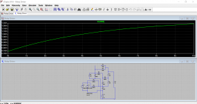
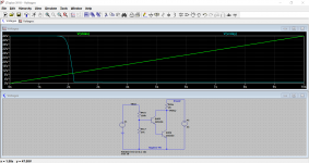
I just threw the relay driver PSU into a simulator to get an idea of what is going on. The voltage across R4 in the diagram here is the important one and that turns on the relay driver transistors. And it comes out correct.
So it did actually work as I first thought even after looking at all the twists and turns
With that 6k8 removed it seems there should be sufficient bias voltage for the transistors to operate.
So those caps need to be checked by substitution first. Did you check the 150k out of circuit?
So it did actually work as I first thought even after looking at all the twists and turns
With that 6k8 removed it seems there should be sufficient bias voltage for the transistors to operate.
So those caps need to be checked by substitution first. Did you check the 150k out of circuit?
Attachments
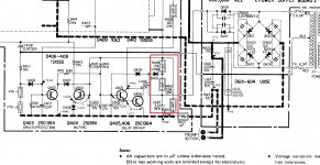
Lets go back to first principles with the relay driver power supply.
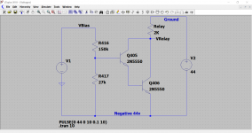
For the relay to energise we must develop sufficient base current in Q405 and Q406 which form a high gain Darlington pair. The actual current needed is very small but we do need to be able to develop at least 1.2 volts across that 27k.
This part of the circuit isn't ground referenced in the normal sense which makes it confusing to work with.
If we take the negative 44 volts (emitter of Q406) as a reference point we should be able to determine when the relay driver will turn on.
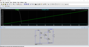
We need to see the voltage on the top end of R416 increase in value (as measured from the -44v rail) to around 8 to 12 volts (guestimate based on typical transistor hfe). This is measured relative to the -44 volt rail, not ground.
So we can simplify the circuit to just this. The relay turns on when we have around 8v or so on the top end of R416 as can be seen here. I have made the bias voltage a rising voltage just to see at what point the circuit activates.
That -2 volts you measured on the base of Q405 earlier could be a clue. I'm wondering if something is suspect with that transistor or even Q406.
Again, going back to my original thoughts on this, with the 6k8 isolated the relay has to operate. So that doesn't leave much .
For the relay to energise we must develop sufficient base current in Q405 and Q406 which form a high gain Darlington pair. The actual current needed is very small but we do need to be able to develop at least 1.2 volts across that 27k.
This part of the circuit isn't ground referenced in the normal sense which makes it confusing to work with.
If we take the negative 44 volts (emitter of Q406) as a reference point we should be able to determine when the relay driver will turn on.
We need to see the voltage on the top end of R416 increase in value (as measured from the -44v rail) to around 8 to 12 volts (guestimate based on typical transistor hfe). This is measured relative to the -44 volt rail, not ground.
So we can simplify the circuit to just this. The relay turns on when we have around 8v or so on the top end of R416 as can be seen here. I have made the bias voltage a rising voltage just to see at what point the circuit activates.
That -2 volts you measured on the base of Q405 earlier could be a clue. I'm wondering if something is suspect with that transistor or even Q406.
Again, going back to my original thoughts on this, with the 6k8 isolated the relay has to operate. So that doesn't leave much .
Attachments
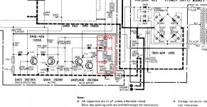
Just for info...
Although this part of the circuit isn't ground referenced we can still measure voltages from ground as a sort of double check and as a reality check.
The -44 should of course then be -44 and the voltage on the top end of R416 will be around -36 as a minimum point the circuit should operate. If the -36 were closer to zero , so -30 or -20 for example then we have even more current available leaving no doubts it should work.
you can measure V1 to V3 voltages to ground or check their resistances out of circuit
Hi Patrick, thanks for suggesting. The voltages are:
V1: 23.4 V
V2: -16.36 V
V3: -32,20 V
To me seems all over the place. Does that help?
Eschenborn
- Status
- This old topic is closed. If you want to reopen this topic, contact a moderator using the "Report Post" button.
- Home
- Amplifiers
- Solid State
- Sony TA-3650 power rail resistors burn