I feel obliged to comment on your "findings", minek - because mine are very different. 🙂 (Possibly because I don't keep rotating amps ... I build a new one, confirm (with a listening team!) that it sounds better than the previous one - and get rid of the previous one! 🙂 )
I've done this over many years with Hugh's amps, driving my 3-way active Maggies; AKSA 100N+ plus two 55N+s gave way to a Soraya 100 plus two Lifeforce 55s ... which gave way to a Soraya 100 plus two NAKSA 80s.
A few months ago, having finished building two AN 4Rs to drive the 3ohm mids & 2ohm ribbons of my Maggies, Hugh came over for a listen. I myself "thought" the Maggies sounded better than with the NAKSAs ... but it was a close call. So I was a bit disappointed at having spent so much money and so much effort building these amps.
Today, Hugh came over again ... to listen to the AN 4Rs driving the new spkrs I had designed - which have replaced my Maggies.
He was blown away by how the AN4 Rs sounded with the new spkrs - so much better than with the Maggies. 🙂 We listened to a 'Test' CD of his that he knew well - and Hugh said that he was hearing stuff on the CD for the first time! 😎
So resolving spkrs would appear to be an essential part of comparing amps.
In case anyone is interested, below are pics of my new "zero baffle" spkrs. They:
* are 2-way active
* hand over to my subs at about 150Hz (still playing with that)
* use SB Acoustics 'Satori' drivers, and
* need a miniDSP or DEQX to provide the 24dB XOs and some mid/bass driver EQ.
Andy
Wow Andy - completely baffle less! Do you have a separate thread for your build and further details?
yep but you must do a 2,5 way with passive xo ....
Que? I think you are confoosed. 🙁
Andy
The amp is directly connected to the drivers:
the high pass filter is between preamp and amp,
it's only a small nF cap in series before the amp.
This gives you only a first order electrical slope, but there's no need for the DSP with its AD-DA conversions.
Only doable if a simple first order electrical is sufficient and you don't need the extra DSP functionality
Sorry, Danny ... we seem to have a different definition of 'things'. 🙁
In my world ... an amp is directly connected to a driver if there is nothing in series between the amp and the driver! No inductor (for a LP filter) and no capacitor (for a HP filter).
Sure I could put a cap before the amp, to perform as a HP filter (letting the amp still be directly connected to the tweeter) - but this delivers only a 6dB slope. As I am already taking the tweeter down as low as I think it will go (before 'cone breakup') ... I need a 24dB slope between it and the mid/bass driver.
And wrt "AD/DA conversions":
* I have digital sources, as well as analogue (ie. my phono stage)
* I use a DSP unit to provide steep XOs and room EQ - plus delay on my 'mains' ... to correct for the fact that my subs are about 5' further away from my ears than the mains are.
* so a 'DSP unit' is a given in my setup.
* I have 4 sources - of which 3 are digital:
- my CDP
- my DAB+ tuner,and
- my TV set-top box.
* so by feeding these digital sources directly into the digital input of my miniDSP unit ... I am saving a D2A and an A2D conversion step for these sources.
* and by using an external A2D converter on my phono stage ... I get to use a much higher quality A2D converter than the chip provided in my miniDSP unit. 🙂
Andy
Last edited:
Wow Andy - completely baffle less! Do you have a separate thread for your build and further details?
Thanks, sn. 🙂
I have not posted on diyAudio ... but I have on Stereo Net Australia (SNA).
See here:
The spkrs which are replacing my Maggies - DIY Audio Projects - StereoNET
Regards,
Andy
Hi Andy,
I see now that you have 6 channel amplification,
so bass, mid and high have each its amplifier.
I thought that mid-high was one amplifier, from there the confusion.
Yes, for OB correction and 24db slopes it's easy and flexible with DSP,
and by using an external AD converter you got that also covered 🙂
Bonsai,
rtHz worked.
I tried to measure noise floor from Laptop/battery and with very short USB cable, it is at approx -155dBV. Looks much better.
It has no spikes under 1kHz, and few, very short spikes after 3kHz.
Long USB cable was not good..
>What are your external gains?
-155dB above is measured with 'input gain' in dbV options set to 0.
When measuring real amp, in dbV options,
'input gain' is set to -20 dB (attenuation - my load is 8 Ohm + 0.8 Ohm, and I'm picking up signal from 0.8 Ohm resistor)
What are your external gains?
The spot noise floor (that’s the noise at a specific point in the measurement window and usually taken as 1 Hz BW) with the inputs shorted, no external gains, 50 averages and 20 kHz measurement BW should be about -150 to -155 dBV. If you integrate this noise over the measurement BW and do not average it, the total noise is specified -113 dBV. To read the noise accurately you must tick the ‘rtHz’ box in the dBV dialog box (note carefully the caveats associated with this wrt reading signal peaks in the manual - so only tick this box when you want to measure noise).
Last edited:
The spikes after 3 kHz are probably external noise sources and nothing to do with the measurement system or you amp under test. A big problem is at c. 16 kHz - I think this is the LED display sync or refresh rate that a lot of folks pick up in their measurements.
I'm pretty busy at the minute, but will try to post up a video in the next few days. I'm no expert at this stuff, but having a sound card or a QA401 is only half way to where you need to get to - ensuring the measurement environment is right so you get repeatable, believable results is a much bigger challenge and as I mentioned earlier, a steep learning curve.
I'm pretty busy at the minute, but will try to post up a video in the next few days. I'm no expert at this stuff, but having a sound card or a QA401 is only half way to where you need to get to - ensuring the measurement environment is right so you get repeatable, believable results is a much bigger challenge and as I mentioned earlier, a steep learning curve.
Thanks Bonsai!
Measurement is one thing.
But I'm thinking now - if our 'electrical environment' is so bad, all these amps designed and built with huge effort,
are being affected in negative way by all these ground loops, magnetic fields, etc.. It's almost like it's not worth building good amp, because final result will be degraded anyway.
Wonder if there is a way to minimize this degradation?
I mean I bet there is, but how practical/expensive it would be..
When designing my PSU and grounding, I followed your guidelines, but what else can be done?
I tried to put auto-transformer between my amp's PSU and mains - it didn't make any difference..
A lot of this stuff is below the threshold of audibility - not that’s its an excuse to let it go.
With careful layout and attention to minimizing loop areas in the wiring and PCB, you should be able to get the peak noise (hum, signal harmonics from wiring/trace induction etc) components below -90 dBV and at or below -110 dBr at full power.
So it is a worthwhile pursuit - and this is definitely the most challenging party of amplifier design 🙂
With good grounding scheme and a quiet PSU (this is actually a linear 400VA 25v trafo and active bridge CRC cap Mx), one can get a very low noise floor. Here is the LuFo SE Class A amp running at 3.0A bias current. The noise floor is -125dB, the 60Hz peak is just radiated EMI pickup (present when amp is off).
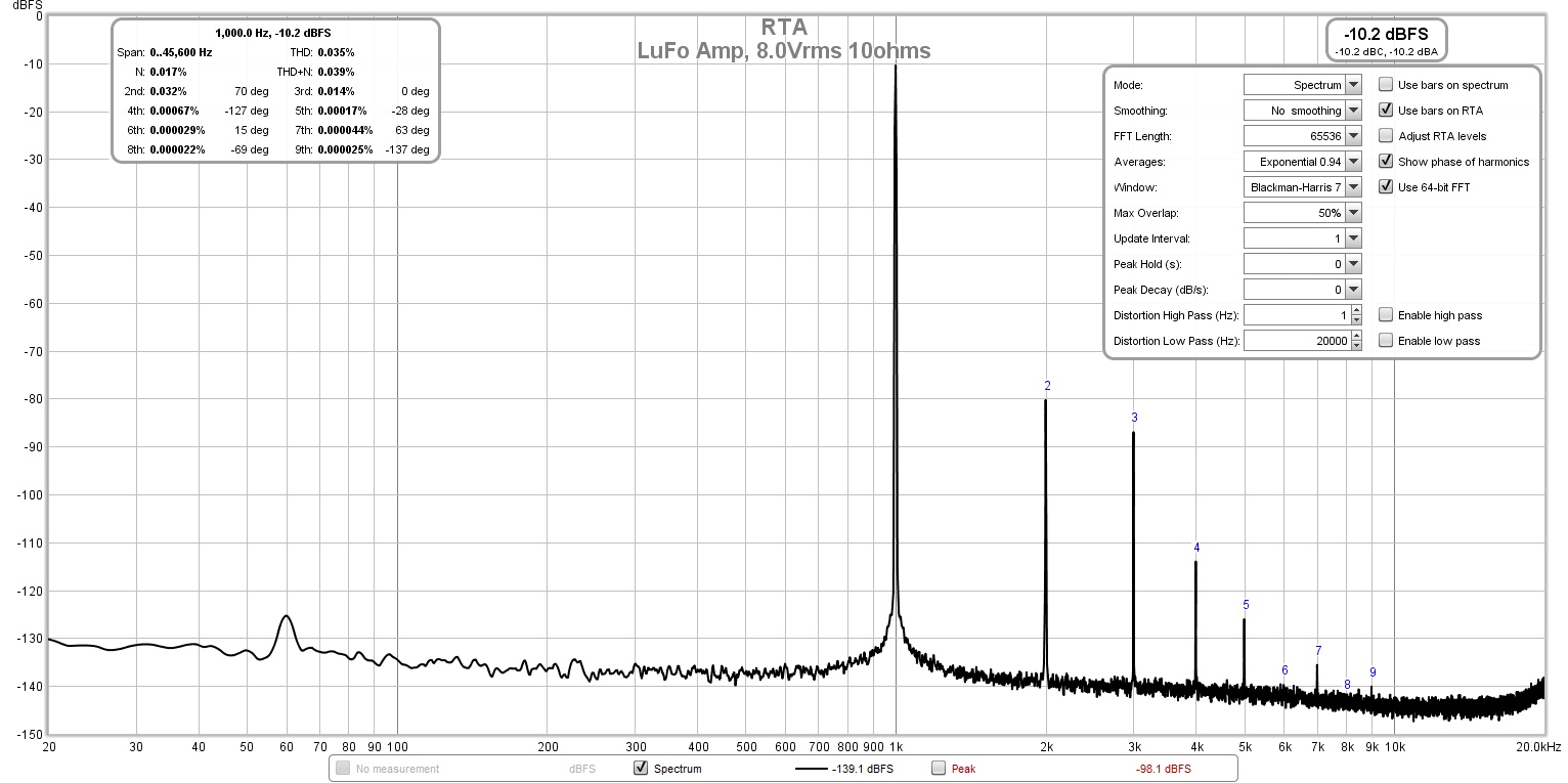
This makes for an amp that you cannot tell it is turned on with ear pressed to speaker cone.
Q3 dissipates some heat, although 2N5551 would work, it would not be ideal. You can use 2N5401 instead of KSA992 though.
This makes for an amp that you cannot tell it is turned on with ear pressed to speaker cone.
Q3 dissipates some heat, although 2N5551 would work, it would not be ideal. You can use 2N5401 instead of KSA992 though.
Last edited:
Extraordinary results........
X,
To achieve those figures you must have:
1. Superb design with a very quiet active device,
2. Meticulous earthing,
3. Unusual topology for a SE with very high PSRR, and
4. An effective cap multiplier.
Congratulations for very good results, better than most top shelf SS ultra high quality offerings.
Of course, you do not have voltage amplification on the LuFo, but even with a reasonable front end your noise would not be worse than 119dB, given the 125dB figure you achieve as a buffer. If you use a tube, the S/N ratio will drop significantly of course, but you'd expect that with an AC filament. A DC filament might reduce it to almost nothing as long as B+ is quiet too.
Hugh
Thank you, Hugh.
The design was a hand soldered P2P on veroboard, and the meticulous earthing was a bit of spaghetti - but all there (heatsink, frame, earth connected) and clean and dirty ground separated by an NTC. 🙂
The data presented is with a 22dB gain solid state preamp of your design - and the preamp is powered with a 12v Class 2 wall wart driving a DCDC step up. I also have a tube preamp/hybrid that uses a DCDC converter for 6.3v filament and indeed, the noise floor is similarly low and quiet - inaudible at -125dB.
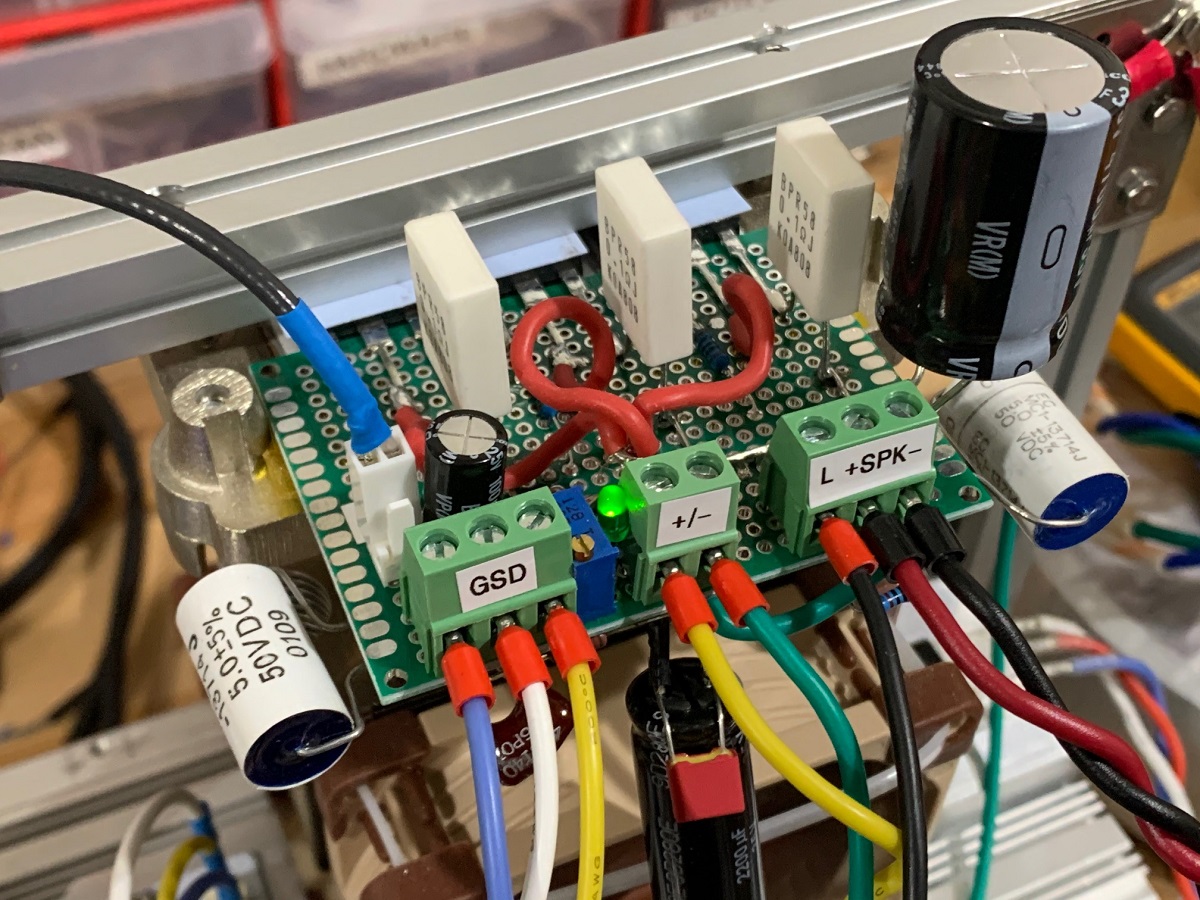
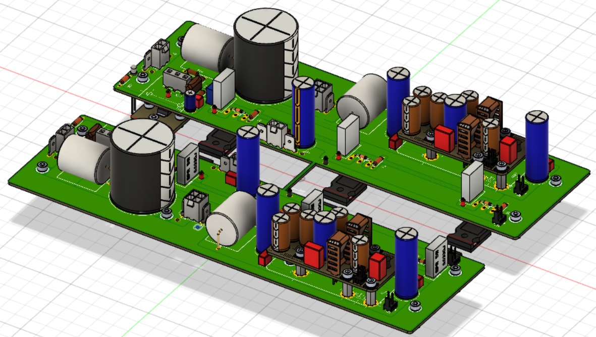
The amp:
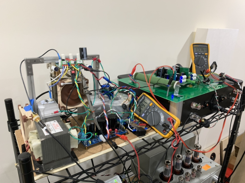
Here is what the amp and measurement setup looked like:
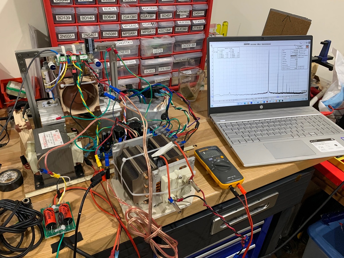
In the listening space, it is cleaned up a bit more for the 39w continuous sine wave test for 30 min:
Here is a closeup of the quiet output device - an LU1014D/LD1014D mounted on an aluminum substrate PCB and heatsink:
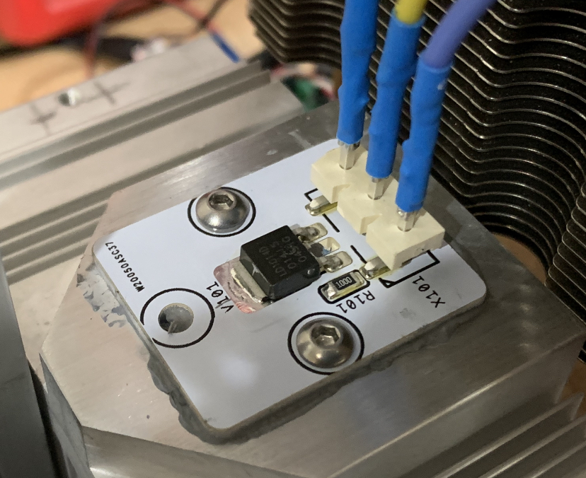
The specs on this device says it can take 50A continuous load. I have run it at 6A - no sweat.
BTW, JPS64 designed another masterpiece PCB for this amp (designed for conventional passive heatsinks) - coming soon!
The design was a hand soldered P2P on veroboard, and the meticulous earthing was a bit of spaghetti - but all there (heatsink, frame, earth connected) and clean and dirty ground separated by an NTC. 🙂
The data presented is with a 22dB gain solid state preamp of your design - and the preamp is powered with a 12v Class 2 wall wart driving a DCDC step up. I also have a tube preamp/hybrid that uses a DCDC converter for 6.3v filament and indeed, the noise floor is similarly low and quiet - inaudible at -125dB.
The amp:
Here is what the amp and measurement setup looked like:
In the listening space, it is cleaned up a bit more for the 39w continuous sine wave test for 30 min:
Here is a closeup of the quiet output device - an LU1014D/LD1014D mounted on an aluminum substrate PCB and heatsink:
The specs on this device says it can take 50A continuous load. I have run it at 6A - no sweat.
BTW, JPS64 designed another masterpiece PCB for this amp (designed for conventional passive heatsinks) - coming soon!
Last edited:
Hi TT,
Most of it is described in this thread.
Howto - Distortion Measurements with REW
My setup has evolved a bit. Don’t use wire wound or metal oxide resistors for distortion measurements. My current rig is this:
Focusrite 2i4 Gen2 with USB connection to HP Pavilion laptop (i7 and Win10) running on batteries for most critical measurements. Free REW software in ASIO mode at 192kHz and 24bit for measuring the FFT. Victor’s low distortion (ppb THD and powered with 4x 9v batteries in series) 1kHz oscillator source. A homemade balanced ~10:1 voltage divider using circa 20k:2k Dale CMF55 resistors, Audyn Q4 4.7uF 250v MKP AC coupling caps between the divider and the balanced XLR inputs to the 2i4. I cut a commercial XLR mic cable (nicely shielded and supple wire) to use XLR connector end ankong flying leads on other end. Ground in the XLR is tied to amp chassis with 8ohm NTC. Load resistor is low inductance bulk metal film EBG UXP-300 10 ohm 300w resistor with cpu cooler heatsink and fan. Vrms measured using Fluke 101 or 115 meter and digital O-scope for trace monitoring of clip check at max power.
Last edited:

It’s pretty neat what we can do with consumer grade electronics nowadays for an analyzer that would have cost a small fortune 20 years ago.
- Home
- Amplifiers
- Solid State
- Alpha Nirvana 39w 8ohm Class A Amp