It is the wrong amp for 4 ohm speakers.
It runs out of OLG (which is load dependent with this topology) and distortion goes up.
Zout is also too high for low impedance load.
Of course one can get round that by changing the topology.
But that was NOT the mission.
So before someone complains it does not sound good with their speakers,
he needs to find out what this is designed for in the first place.
Cheers,
Patrick
Got it. I have no problems design an 8ohm loudspeaker for this amp. Usually 8ohm is better in order to avoid too much current demand.
This amp check some boxes for me, so will build it so I can start playing around with Linkwitz-Riley filter 🙂
This amp check some boxes for me, so will build it so I can start playing around with Linkwitz-Riley filter 🙂
I did a quick sum for the cost of one channel from Mouser.
Without the optional servo, one channel will cost less than 20€.
The most expensive item is the 3296X trimpot.
But you can of course use a cheap one for setting and then replaced with fixed resistors later.
I always replace trimmers with fixed R's anyway.
The servo will add another 8€, the opamp alone 2.60€. 🙂
Patrick
As I already have virtually all components I shall build this amp. Patrick, Many Thanks for another well thought out design.
Of course there ia always a hidden extra cost...in my case a pair of higher impedance high sensitivity speakers to be built! :roll eyes: I was looking for an excuse anyway....just as soon as the gout has gone and I can use my elderly hands again. 🙂
Of course there ia always a hidden extra cost...in my case a pair of higher impedance high sensitivity speakers to be built! :roll eyes: I was looking for an excuse anyway....just as soon as the gout has gone and I can use my elderly hands again. 🙂
Can I ask now that Patrick has made the final design available with the associated gerber files, is any member giving any thought to getting some pcb's made up and perhaps doing a small GB, I for one will happily put my hand up to buy 2 of these for a stereo amp. No hurry though.
Cheers,
Gary..
Cheers,
Gary..
Hello Patrick,
Can I ask if the pcb has through hole lands to take the Toshiba 2SK389 dual Fet package as I have these that I can use instead of the SMD 2SK209's.
Without seeing a photo of the board layout, I thought I would ask you directly on this - perhaps you have it laid out so it will accept the 2Sk389 dual package or individual 2SK170 BL's and the SMD device for the input Fets.
Now I have just seen post #91, that probably explains that an adaptor pcb needs to be used for the 389 and 170 devices.
Regards,
Gary..
Last edited:
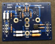
The alpha tester reporting here...
I must say that this was highly educational and fun project for me and it was an honor to help Patrick with this design. This was just my second power amplifier build after all of the headamp projects but still I managed to pull it off with Patrick's vast knowledge and fast response to whatever problems and questions.
Now that the final tweaks and development has been done I'm sure that this could be carried by maybe even for beginners with some basic electric skills.
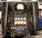
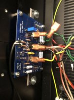
The listening test is still pending on my side because I ordered only 2 pcs of the FQAs for testing and now I need to have some more and do matching between channels. Unfortunately my speakers are of 4 ohm impedance, but we'll see how the UDNeSS performs with them.
I attached a couple of pics from the testing phase. I used the chassis from my M2x build that has the diyAudio UMS drilling pattern and I was able to fit the MOSFETs in existing tapped holes but the standoffs require new tappings. Let's hope we see many more builds in the future. 🙂
I must say that this was highly educational and fun project for me and it was an honor to help Patrick with this design. This was just my second power amplifier build after all of the headamp projects but still I managed to pull it off with Patrick's vast knowledge and fast response to whatever problems and questions.
Now that the final tweaks and development has been done I'm sure that this could be carried by maybe even for beginners with some basic electric skills.
The listening test is still pending on my side because I ordered only 2 pcs of the FQAs for testing and now I need to have some more and do matching between channels. Unfortunately my speakers are of 4 ohm impedance, but we'll see how the UDNeSS performs with them.
I attached a couple of pics from the testing phase. I used the chassis from my M2x build that has the diyAudio UMS drilling pattern and I was able to fit the MOSFETs in existing tapped holes but the standoffs require new tappings. Let's hope we see many more builds in the future. 🙂
Attachments

Last edited:
> Many Thanks for another well thought out design.
A lot of the work was done by Morde, our Alpha tester.
So all thanks go to him.
The best you can do for us is to build this, properly.
Do all the matching, setting up, trimming and measuring, etc.
Morde will share his experiences.
It is just as much about the building as the end product in the end.
So don't miss the DIY fun.
And then come back to share your experience.
Patrick
PS The FQA9P25 is a good part.
It is also a bargain.
I cannot understand why it is not more widely used.
A few comments on the Alpha build :
1) Make sure the wiring from CRC to amp PCB is as short as possible.
2) During tests the servo was disabled. We suggest you only add the servo if needed.
__ In any case adjust the DC offset without the servo.
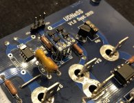
3) The ideal placement of the 2SK209 adaptor is vertical.
__ This allows shortest wiring to the amp PCB, as well as access to other components.
You can use my J2K3497 layout for reference :
FirstWatt J2
This case does not have the ML engraving and is good quality for the money.
JC3 circuit power amplifier aluminum chassis enclosure with both side radiator | eBay
Of course no comparison to the F5X case. 😉
Patrick
1) Make sure the wiring from CRC to amp PCB is as short as possible.
2) During tests the servo was disabled. We suggest you only add the servo if needed.
__ In any case adjust the DC offset without the servo.
3) The ideal placement of the 2SK209 adaptor is vertical.
__ This allows shortest wiring to the amp PCB, as well as access to other components.
You can use my J2K3497 layout for reference :
FirstWatt J2
This case does not have the ML engraving and is good quality for the money.
JC3 circuit power amplifier aluminum chassis enclosure with both side radiator | eBay
Of course no comparison to the F5X case. 😉
Patrick
first of all, thank you for that beauty Patrick
can we add aditional 2 x FQA to output as per first post schematic for better handling with less than 8 Ohn or If we like to higher rails with few volts
can we add aditional 2 x FQA to output as per first post schematic for better handling with less than 8 Ohn or If we like to higher rails with few volts
The alpha tester reporting here...
The listening test is still pending on my side because I ordered only 2 pcs of the FQAs for testing and now I need to have some more and do matching between channels. Unfortunately my speakers are of 4 ohm impedance, but we'll see how the UDNeSS performs with them.
I attached a couple of pics from the testing phase. I used the chassis from my M2x build that has the diyAudio UMS drilling pattern and I was able to fit the MOSFETs in existing tapped holes but the standoffs require new tappings. Let's hope we see many more builds in the future. 🙂
I have to admit that I do not understand why people has to ask me (or anyone else for that matter) for PCBs.
You have the Gerber files (already published).
You can order them at the likes of SEEEDStudio for less money than the postage.
So what is the problem of ordering yourself ?
Cheers,
Patrick
You have the Gerber files (already published).
You can order them at the likes of SEEEDStudio for less money than the postage.
So what is the problem of ordering yourself ?
Cheers,
Patrick
Morde has done some more measurements on DC drift.
Of course it depends on your heatsink size and also insulation in between.
From power up at 0V DC, the offset went to -22mV in 5 minutes, but dropped back to 16 mV in an hour.
Once reset to zero, it stayed stable within +/-2mV.
So you can leave out the servo without any problems.
In any case, you should only add the servo after setting the DC offset properly on the heatsink to be used.
The servo circuitry will also be tested in the next days, just to be sure.
Again all thanks to Morde.
PS
It is well known that I only use Kerafol. And most likely the first one to do so at DIYA.
Mica and Goop
https://linearaudio.net/sites/linearaudio.net/files/v3 euvl.pdf
Patrick
And is there difference in sound with J2? It's not hard to get the same harmonic profile with this kind of simple circuits, is there a point except one can use mosfet instead of power jfet?
> is there a point except one can use mosfet instead of power jfet?
Yes, as stated in post #1 and in the article.
All active devices in the J2 are unobtanium.
(I do not consider LSJ74 to be equal to 2SJ74, backed up by measurements already published.)
All active devices proposed here are readily available from Mouser and Digikey.
> And is there difference in sound with J2?
Subjective impressions you will have to find out yourself.
> It's not hard to get the same harmonic profile with this kind of simple circuits
I welcome you to show us how, perhaps also without using 2SK209's and FQA9P25's ?
Cheers,
Patrick
I have to admit that I do not understand why people has to ask me (or anyone else for that matter) for PCBs.
You have the Gerber files (already published).
You can order them at the likes of SEEEDStudio for less money than the postage.
So what is the problem of ordering yourself ?
Knowledge. Never done that, don't know how to do it.
Just an example: I ordered my PCBs from PCBway.com. You upload the gerber zip file (provided by Patrick) directly into their ordering system and they will evaluate it and once you have approval you can order them. It is made very easy. I hope this helps.
And here is an online tool you can use to see how the pcb looks like after you upload the gerbers.
Online Gerber Viewer
And here is an online tool you can use to see how the pcb looks like after you upload the gerbers.
Online Gerber Viewer
Last edited:
If ordering PCB is too difficult, then the rest of the project must be humanly impossible.
The easiest is of course just to order a J2 from Nelson.
Perfect results guaranteed.
And you'll be looked after for life.

Patrick
The easiest is of course just to order a J2 from Nelson.
Perfect results guaranteed.
And you'll be looked after for life.
Patrick
> is there a point except one can use mosfet instead of power jfet?
Yes, as stated in post #1 and in the article.
All active devices in the J2 are unobtanium.
(I do not consider LSJ74 to be equal to 2SJ74, backed up by measurements already published.)
All active devices proposed here are readily available from Mouser and Digikey.
> And is there difference in sound with J2?
Subjective impressions you will have to find out yourself.
> It's not hard to get the same harmonic profile with this kind of simple circuits
I welcome you to show us how, perhaps also without using 2SK209's and FQA9P25's ?
Cheers,
Patrick
Haha, so I should buy J2 and make this amp also.. 😁 I'm interested in subject because I'm working on the similar topology. Nice work, cheers.
Couldn't agree more that you have made life very easy for anyone to order PCBs - as a first time user of PCBway , they gave me a $5 coupon at checkout and using the zipped gerber files it took all of 5 minutes to order both boards for a final cost of $13 shipped in 10 days. Gone are the days of home etching , this is very easy..dB
- Home
- Amplifiers
- Solid State
- UDNeSS, or You don't need Semisouth's