You can do it differently.
Opamp and transistors operate on a common load.When the transistors are closed, the signal comes from the output of the operational amplifier.
Distortion is reduced
Putting resistors on the power supply of an amplifier is definitely not a good idea, neither is the idea of playing with the inner work of an amplifier as their designs are different.
Anyway, this thread is not for this, but, I guess, any comments are welcome.
@stanislav1957 This method you are talking about would deserve much more attention. The following page is from a german book: U. Tietze Ch. Schenk: Halbleiter - Schaltungstechnik (Springer-Verlag 1999) . It seems to be this is one of the most effective ways to achieve realistic sound. The Hungarian-based Gauss Audio is developing their amplifiers based on this method. As far as I know, they have developed similar but a more effective solution to decrease crossover and impulse distortions, than described in book I mentioned.
The resistor between the bases and the emitters may slow the circuit response.
In regards to the resistor between the bases emitters :
Other than slowing the circuit, because, the resistors takes current from the amplifier, which does not go through the base emitter junctions of the transistors, the idea of a base emitter resistor, as per your Figure 5.20, is excellent.
Amplifiers have an internal protection which would not allow a current greater than a given value, such as 100mA to 140mA for LM7171, but, still, the base emitter resistor helps.
The transient current through the base emitter capacitance has a similar effect.
The circuit with a base emitter resistor was described where the pure Darlington configuration was described in the second document.
I am not sure whether the resistor will speed or slow the transient response. Has to be tried in practice.
I do not recall whether I have tried this or not, however, I am unable to easily try now, because of Co, which prevents any evaluation and, also, because I do not have the emitter's connection conveniently to, just, wire a resistor externally and I do not want to open the amplifier and attach new wires. I may be able to do this, but, I am not able to unsolder Co easily.
In case anyone wants to make the simple schematics themselves, they can leave room on the board for the resistor as well as for a few capacitors in parallel to make a Co. Then, they can test the circuit without anything and, then, they can install the base emitter resistor. A lower than 68 Ohm value is also welcome, but, the power dissipation by the amplifier must be considered as there will always be an additional current 0.7V / resistor.
Then sorry for intruding on your topic
Nothing to be sorry. I am happy you have posted the solution, which is extremely innovative and original.
Thanks to you and another poster, I have written a document on the solution with a resistor between the base and the emitter, which I will publish soon. The gradual opening of a relevant transistor may eliminate or decrease the machine gun noise.
I like the idea and, as per another poster, the idea is related to your post too, so, thank you very much and keep posting.
Also, your solution seem to be generally accepted all over the world.
I have just uploaded a file, called : " Between the Base and the Emitter.doc " in the same folder :
Amplifier - Google Drive
This document discusses the idea of the base emitter resistor to allow for the amplifier to regulate during the crossover transition. The document may be updated.
Amplifier - Google Drive
This document discusses the idea of the base emitter resistor to allow for the amplifier to regulate during the crossover transition. The document may be updated.
Hi Steven,
Sorry, I didn't respond to your post asking I try your circuit. I have been away for a while. I'm thinking about it.
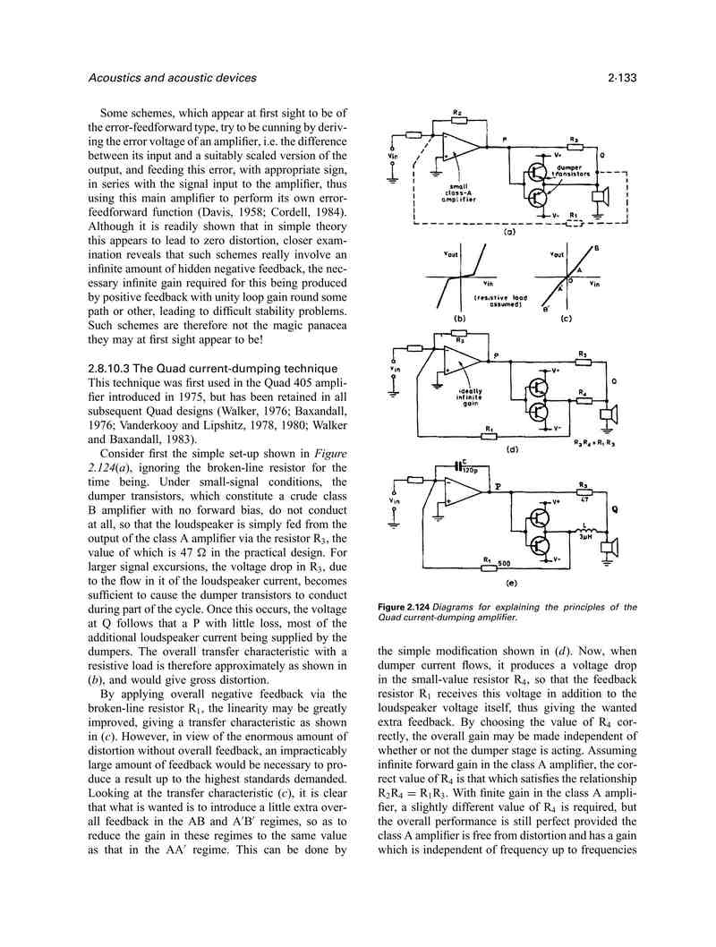
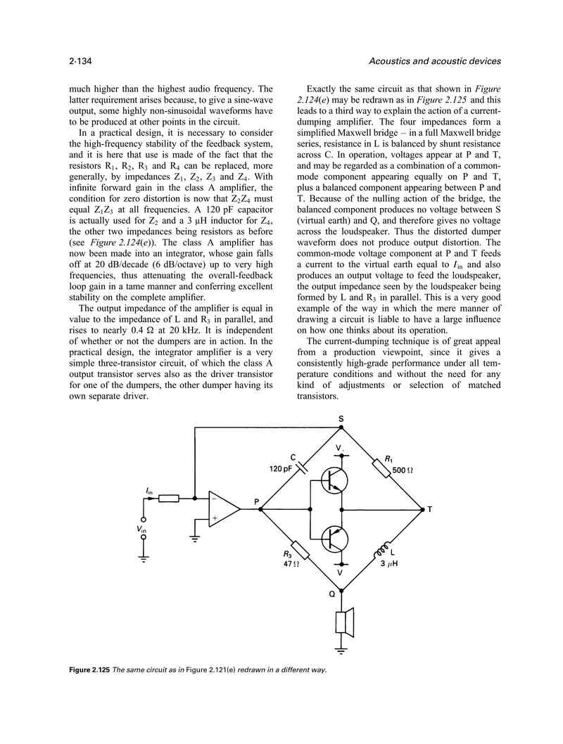
About your base-emitter resistor mullings I recall Peter Walker developed current dumping around it and got knighted for his creation. Peter Baxandall wrote a simple explanation of its development in Michael Talbit-Smith's Audio handbook and I attach the two relevant pages (assuming it's legit) since you are following a similar path of development here") . R3 in this text is the "base-emitter resistor".
. R3 in this text is the "base-emitter resistor".
To read it save the file and open in a picture viewer.
Sorry, I didn't respond to your post asking I try your circuit. I have been away for a while. I'm thinking about it.
About your base-emitter resistor mullings I recall Peter Walker developed current dumping around it and got knighted for his creation. Peter Baxandall wrote a simple explanation of its development in Michael Talbit-Smith's Audio handbook and I attach the two relevant pages (assuming it's legit) since you are following a similar path of development here
. R3 in this text is the "base-emitter resistor".To read it save the file and open in a picture viewer.
Attachments

Last edited:
The document, mentioned in the previous thread, has been updated with a couple of paragraphs, just before point 2.
Some mistakes have been found in the document. Some have been corrected, but, a closer look is required, thus, the document is not corrected yet, but, will be, hopefully.
Another post will be made to notify when the document is corrected.
I am happy with the base emitter resistor, however, I have one concern : because the resistor has Ube over when a transistor is open, the resistor requires current from the amplifier and the power limitations of the amplifier do not allow some very tiny resistor of a few Ohms but, instead, require a resistor of a few tens of Ohms, say, 47Ohms.
I am afraid the amplifier output may rise too quickly and, thus, open a transistor too quickly. I am not sure whether this will be slow enough to eliminate the machine gun noise, i. e., whether the transistors will open gradually enough to also avoid the digital systems style switching noise ( at 20KHz ).
Definitely will open slower than without the resistor. But, a normal value Co cannot be installed, so, will the delay be enough?
Hopefully, yes. Must be tried.
I have update the document " Between the Base and the Emitter ", viewable here : Amplifier - Google Drive
Scroll with Ctrl + End to the very bottom where Figure 8. and Figure 9. are. These are related to a circuit which I have not made, yet, but, I intend to make to see what happens.
I, usually, post schematics after I have made and tested them, but, in this case, I will not be able to make the circuit very soon and I have decided to post the idea.
Any comments?
By all means, a complementary feedback pair is a better idea in this case and should be included in the document.
The same base emitter resistors are still necessary.
However, there is one great disadvantage, I think, but, not in this case :
When the amplifier output voltage, applied to the base, can reach close to power supply, the secondary transistor may be close to become closed and, then, the amplifier has to provide the current. This will overload and burn the amplifier.
In this case, however, the amplifier cannot reach even close to power supply, so, a complementary feedback pair is OK.
I will update the document.
- Home
- Amplifiers
- Solid State
- Amplifier