Interesting development. I think that I "feel" where this concept is intended to be going, but I am not sure about some details here.
a). What does 'Zener 0V' mean?
b). As soon as D1 starts to conduct, T11 switches on. Will it not fail? (I am afraid that at start of conduction of T11, jointly T11 and T12 will create an inter-rail conduction path, a "short", with no limit to the current, and this could result in failure of these transistors).
c). In this transistor-assisted-Schottky concept, that you are thinking about, would the condition be fulfilled / met, that the Schottky diodes are conducting constantly, all the time? Or would they have periods where the one or the other is inactive? My gut feeling tells me, that the Schottky diodes "should" be conducting all the time, but maybe you see some alternative mechanism, concept, solution here? What is the intent?
===
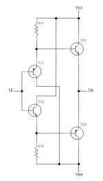
Was thinking about how "not to interfere" with your design goals (resistors, capacitors, et al). Was thinking about how to "force" a constant current flow through the Schottky diodes, irrespective of the fact that they are riding "on the signal", or "floating" on the signal and jumping all around across all possible values ranging from the plus supply rail to the minus supply rail. How do you make a "floating" CCS-CCD pair? I don't know. Not sure. I tried to envision such a "floating CCS-CCD pair" that would be capable of floating on the output of your op-amp, and (possibly/hopefully) not interfering with your circuit too much.
I came up with this stuff. A combination of two series connected CCS (top side) and CCD (bottom side). But in order so as not to antagonize them against each other (so that they do not "fight" against themselves), added a mirror. Result: hopefully a "floating" current source. Probably nonsense. But maybe? Just take a look. Should this floating CCS-CCD be powered from a separate DC power source, or can it be powered from the same Rails as your amplifier? Not sure. The safer bet would be to power it from something separate. But maybe it could also be powered from Your rails. Then You probably would "loose" some 2 volts of your maximum possible output swing. But my bigger concern is that if powered from "Your rails", then there is the risk of various "capacitance" or other problems likely to emerge. Whereas when powered from a totally "separate" power source, there is a higher chance that the floating CCS-CCD would not in any way "interfere" with your low-capacitance Op-Amp concept. Just thinking out loud, fishing for some alternative ideas.
How about conducting a "Simple and Stupid" experiment? Because if no practical value gained, then not worth all the talking. A 9V battery. In series with a 3k9 resistor. Voila! A KISS floating current force. Two Schottky diodes, ... and Rock and Roll. Hopefully.
Here is another variation of your schematics which I like a lot because of the clever addition of + and - 0.7V and double buffering. The only problem is the availability of resistors.
Attachments
Looks like a Diamond Buffer, and probably is a very good idea.Here is another variation of your schematics which I like a lot because of the clever addition of + and - 0.7V and double buffering. The only problem is the availability of resistors.
I was wondering ... Tubecad proposed some time back a "speed-up" capacitor in the scheme, but I suppose that you do not like any sort of capacitors ...
https://www.tubecad.com/2012/09/22/Diamond Buffer with Capacitor.png
Here is his full article. I suppose that it would not hurt to browse through some of those ideas, maybe something may come in handy?
Might Diamonds
John Broskie also mentions adding additional capacitors bridging the emitter resistors. Now that is yet something else altogether. Yeah, yeah ... I know. You hate capacitors ... At least those that create zero's or poll's in the frequency Bode diagram. Do they?
Last edited:
A different take altogether:Here is another variation of your schematics which I like a lot because of the clever addition of + and - 0.7V and double buffering. The only problem is the availability of resistors.
What are your feelings towards DC powered, bi-directional motors?
And to the H-Brigde circuit that controls them?
What is the working of a H-bridge circuit? - Quora
DC Motor Driving using H Bridge
Questions above vaguely relate to a "balanced" (XLR) version of an amplifier,
as would be the case when using two operational amplifiers, as opposed to just one .... Just curious.
The balanced version would require two symmetrical feedback loops.
Balanced architecture would probably open up possibilities to some innovative criss-crossed connections ..
Last edited:
>>>>The only problem is the availability of resistors.
Why can they not be replaced by some form of non-contesting pair of Current-Source-Drain, with the Current Source on top, entangled with a Current Drain on the bottom?
Why can they not be replaced by some form of non-contesting pair of Current-Source-Drain, with the Current Source on top, entangled with a Current Drain on the bottom?
Looks like a Diamond Buffer, and probably is a very good idea.
I was wondering ... Tubecad proposed some time back a "speed-up" capacitor in the scheme, but I suppose that you do not like any sort of capacitors ...
https://www.tubecad.com/2012/09/22/Diamond Buffer with Capacitor.png
Here is his full article. I suppose that it would not hurt to browse through some of those ideas, maybe something may come in handy?
Might Diamonds
John Broskie also mentions adding additional capacitors bridging the emitter resistors. Now that is yet something else altogether. Yeah, yeah ... I know. You hate capacitors ... At least those that create zero's or poll's in the frequency Bode diagram. Do they?
I do not think such a capacitor would speed up the transistors.
I have tried all possibilities to double the transistor capacitors, Cbe, (may be Cce, do not remember ) and Cbg ( base to ground ). No effect.
A different take altogether:
What are your feelings towards DC powered, bi-directional motors?
And to the H-Brigde circuit that controls them?
What is the working of a H-bridge circuit? - Quora
DC Motor Driving using H Bridge
Questions above vaguely relate to a "balanced" (XLR) version of an amplifier,
as would be the case when using two operational amplifiers, as opposed to just one .... Just curious.
The balanced version would require two symmetrical feedback loops.
Balanced architecture would probably open up possibilities to some innovative criss-crossed connections ..
Yes, they use common emitters. Problem : base resistor.
>>>>The only problem is the availability of resistors.
Why can they not be replaced by some form of non-contesting pair of Current-Source-Drain, with the Current Source on top, entangled with a Current Drain on the bottom?
Yes, current sources may be used. Not sure how faster the circuit would become. Also, transistors can be used with the double buffer, similar to your original idea with diodes.
Your original idea with the diodes is the same as the double buffer. Just your diodes are replaced by transistors. Otherwise, the same. This is why I decided to post the double buffer as a reply to your idea. Otherwise, as I have said, I am not interested.
LOW ESR CAPACITORS
I have looked for low ESR capacitors and found some. Some of them are exotic and expensive, others, good and normally priced.
I am interested in low ESR capacitors rated at >= 16V with values :
1. 0.1uF
2. Any value > 0.1uF and < 1uF
3. 1uF
I have found most capacitors have low ESR around 1uF and from 1GHz to 100GHz with lowest point around 10GHz. Some of them have low ESR at 0.1uF too.
Also, to parallel a few lowers the overall ESR. Of course, the capacitance is added and must not be higher than 1uF, even lower, the lower the better.
Another idea would be to put a low ESR 0.1uF, check the noise and, when necessary, add more in parallel until there is no noise. Hope the overall capacitance would be < 1uF.
Here are the capacitors I have found :
********
Kemet R76 :
250V, 1uF = 2.5mOhms
250V, 0.1uF = 25mOhms
250V, 0.15uF = 17mOhms
Kemet CBR :
Lowest ESR and ESL, but <= 0.1nF
Kemet C0G :
Low ESR and there are all values. ESR = 10mOhm from 1MHz to 100MHz. Should be the best or one of the best.
Kemet X7R :
Manual for all capacitors says ESR = 10mOhms. No information on the X7R Datasheet.
********
CDE Cornell Dubilier : OK but expensive : $4 to $10US
942C :
0.1uF to 1uF = 5mOhms
935C :
1uF = 15mOhms
********
TDK
YFF : 30mOhms for 16V, 0.1uF
X7R around 16mOhms at 10MHz but high when away from 10MHz, from 1MHz to 100MHz
The same applies for Multilayer Ceramic Chip Capacitors such as C0510X5R1C104M030BC ( LOW ESL, 0.1uF, X5R ). However, the 1uF X5R C0816X5R1C105M050AC ( LOW ESL, 0.1uF, X5R ) is OK between 1 and 10Ghz and can reach 3.6mOhms. 1uF has very low ESR, lower than 0.1uF and more stable.
********
Illinois capacitor has some 1.2mOhm capacitors. They are 1kV.
********
A different take altogether:
What are your feelings towards DC powered, bi-directional motors?
And to the H-Brigde circuit that controls them?
What is the working of a H-bridge circuit? - Quora
DC Motor Driving using H Bridge
Questions above vaguely relate to a "balanced" (XLR) version of an amplifier,
as would be the case when using two operational amplifiers, as opposed to just one .... Just curious.
The balanced version would require two symmetrical feedback loops.
Balanced architecture would probably open up possibilities to some innovative criss-crossed connections ..
The fully differential approach has been discussed in the document as well as in another thread. Texas Instruments also suggest a fully differential approach in their document.
A fully differential amplifier can be used to control the two sets of buffer transistors, each set connected to the speaker.
The beauty of this is not only the increased gain, but, most importantly, decreased noise in phase on the two sets. However, the disadvantages are the noise which is out of phase increases, mainly the noise which is 180 degrees off on the two channels of the fully differential approach. Another great disadvantage is the speaker is not grounded and, thus, not referenced to a stable point. This may also increase the noise.
I do not know whether the noise I get is to be in or out of phase. However, a low ESR output capacitor should eliminate the out of phase noise.
Whoever wants to try the fully differential approach is welcome. As discussed in another thread, Texas Instruments and Analog Devices have excellent fully differential amplifiers with 700V/us slew rates and low noise. Of course, two simple amplifiers can always be used instead and an invertor. The invertor can be in the feedback of one of the amplifiers but this damages the symmetry and the in phase noise reduction. External invertor is preferable.
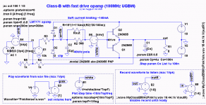
In an attempt to speed up the charge of the output capacitor and the crossover switch of the high power transistors, I have made an additional circuit with an additional push pull buffer, based around very fast transistors. The price to pay is the increased voltage the amplifier has to jump through at crossover from 1.4V ( theoretical ) to 2.8V ( theoretical ). The hope is the fast amplifier can jump quickly over this voltage.
The name of the new document is " Double Push Pull Buffer Amplifier, Class B ". The document is in the same folder where the amplifier has been :
Amplifier - Google Drive
As you have already, probably, noticed, I am interested only in Class B amplifiers. However, you all are not. Thus, I have made and tested a circuit which makes Class B amplifiers into Class AB, provided all these are based on amplifier IC's. I have managed to make this without any resistors on the paths of the base emitter or emitter base currents of the output transistors. I have started a new thread on the topic :
https://www.diyaudio.com/forums/solid-state/361346-buffer-class-ab-amplifiers.html#post6370139
Basic Class-B sims with fast opamps
Hi Steven,
I have now read your latest version closely.

No output capacitor was needed for stability. Adding 1uF across the load shifted the zero crossing point but did not change the jump behavior. Since the closed loop gain is 2 -- use 5V peak for a large swing.
With high frequency and input high voltage swing the slew rates in the jump region are quite high 20V/us but at low frequencies and lower input swings the jump region slew rates turn out to be quite low (0.05V/us). Have a play and see😉.
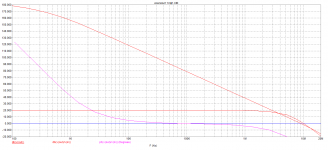
The second attached file does distortion simulations. It includes an approximate weighting filter to our hearing being more sensitive to high-order harmonics in the 1kHz to 3kHz band. For example 10V peak output swing at 100Hz gives a THD of around 0.0003% but the weighted THD is 0.3% or 1000 times higher. This is because most of the distortion harmonics are pushed high into the 20th to 100th harmonic range.
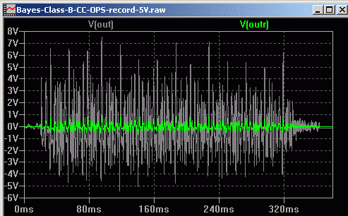
It indicates that for this type of amplifier the usual THD reading is misleading as an indicator of sound quality. Obviously harmonic weighting must be used. The plot below shows the weighting filter signal as V(d2), clearly visible but nothing visible when unweighted V(out).

The third attached file records a clean guitar strum through the circuit above which deliberately has no slew rate limitation to hear if a super fast amplifier "can jump quickly over this voltage" and remove audible crossover distortion. Since the distortion level increases with reducing signal level there are 4 simulations at 5V input, 0.5V, 50mV and 5mV. The record level is boosted at each step so the playback volume is the same - equivalent to getting closer to the speaker with quieter signals. If the distortion cannot be heard with this boosting in the "quieter" recordings then I expect the distortion cannot be heard without this boosting either. The plot below shows the amp output with 5V max input, and V(outr) plot is used to check the recorded level stays below the limit of 1Vpk.
There are prerecorded wave files for those who don't want to run the simulations and just have a listen. It may be some types of music will reveal crossover distortion better than my simple guitar strum example, but I have not tried any other types of music yet. One limitation is this mono 380ms of sound takes 30 seconds to run on my PC, so how long will an entire 4 minute stereo track take to simulate and record?😱.
Next step: simulations with an opamp pole at 3kHz to see if that makes distortion more audible or not. Feel free to try it and report your findings.
Hi Steven,
I have now read your latest version closely.
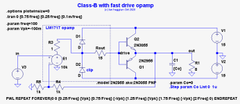
The attached circuit simulates your Class-B idea with a really fast opamp model to see how it behaves ideally without any slew rate limiting. The open loop gain is LM7171 specs 10,000 (80dB) and the output resistance is 15 ohms but no poles....The hope is the fast amplifier can jump quickly over this voltage.
No output capacitor was needed for stability. Adding 1uF across the load shifted the zero crossing point but did not change the jump behavior. Since the closed loop gain is 2 -- use 5V peak for a large swing.
With high frequency and input high voltage swing the slew rates in the jump region are quite high 20V/us but at low frequencies and lower input swings the jump region slew rates turn out to be quite low (0.05V/us). Have a play and see😉.
The second attached file does distortion simulations. It includes an approximate weighting filter to our hearing being more sensitive to high-order harmonics in the 1kHz to 3kHz band. For example 10V peak output swing at 100Hz gives a THD of around 0.0003% but the weighted THD is 0.3% or 1000 times higher. This is because most of the distortion harmonics are pushed high into the 20th to 100th harmonic range.
It indicates that for this type of amplifier the usual THD reading is misleading as an indicator of sound quality. Obviously harmonic weighting must be used. The plot below shows the weighting filter signal as V(d2), clearly visible but nothing visible when unweighted V(out).
The third attached file records a clean guitar strum through the circuit above which deliberately has no slew rate limitation to hear if a super fast amplifier "can jump quickly over this voltage" and remove audible crossover distortion. Since the distortion level increases with reducing signal level there are 4 simulations at 5V input, 0.5V, 50mV and 5mV. The record level is boosted at each step so the playback volume is the same - equivalent to getting closer to the speaker with quieter signals. If the distortion cannot be heard with this boosting in the "quieter" recordings then I expect the distortion cannot be heard without this boosting either. The plot below shows the amp output with 5V max input, and V(outr) plot is used to check the recorded level stays below the limit of 1Vpk.
There are prerecorded wave files for those who don't want to run the simulations and just have a listen. It may be some types of music will reveal crossover distortion better than my simple guitar strum example, but I have not tried any other types of music yet. One limitation is this mono 380ms of sound takes 30 seconds to run on my PC, so how long will an entire 4 minute stereo track take to simulate and record?😱.
Next step: simulations with an opamp pole at 3kHz to see if that makes distortion more audible or not. Feel free to try it and report your findings.
Attachments
-
Bayes-Class-B-CC-OPS-record-5V.zip132 KB · Views: 90
-
Bayes-Class-B-CC-OPS-wTHD.zip11 KB · Views: 85
-
Bayes-Class-B-CC-OPS.zip13.3 KB · Views: 128
-
 Bayes-Class-B-CC-OPS-record-5V.png8 KB · Views: 760
 -
 Bayes-Class-B-CC-OPS-wTHD-zoom.png3.3 KB · Views: 760
 -
 Bayes-Class-B-CC-OPS.png12.1 KB · Views: 871
I have replied to your other post at the " Class AB " thread, which is supposed to be here. Can this be moved?
Anyway, to be clearer, I will repost only part of the reply which I posted in the other thread :
Apply a square wave voltage at the very input of LM7171. The choice of amplitude and frequency is yours ( low amplitudes may have a higher transient period ). How long after the input square wave voltage changes from one amplitude to another does the overall system take to make the output reach the corresponding voltage?
2a. The measurements are to be made without the output capacitor Co
2b. The measurements are to be made with Co = 1uF
In case you prefer, you can put a graphics with three voltages :
1. The overall input voltage ( to LM7171 ), Ui.
2. The overall output voltage ( at the emitters of the transistor ), Uo
3. The output voltage of LM7171, Uoao
Thanks. You have done an excellent piece of work.
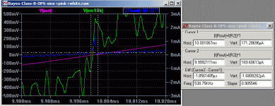
Squarewave input
Hi Steven,
Oh now I see why your other new thread is "Class-AB". You want to explore biasing options in that thread. So this one is for unbiased Class-B. Got it.
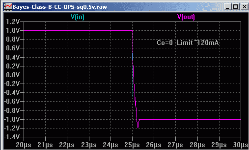
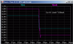
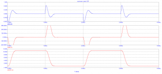
Your request for squarewave plots of Vin and Vout with and without 1uF output capacitors. Current limit is needed with a squarewave due to high slew rates.
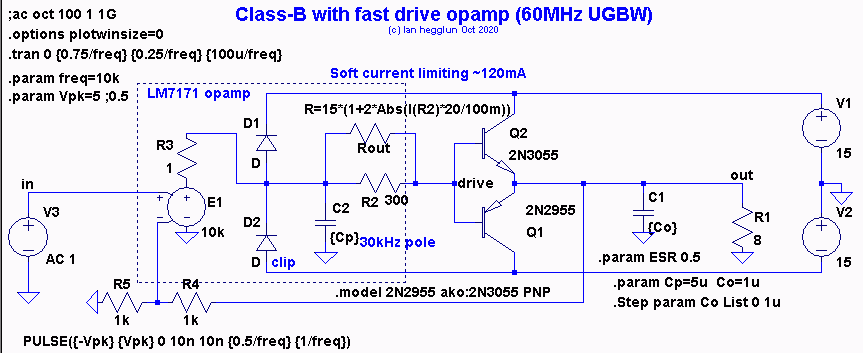
It is difficult to model current limiting with a simple opamp macromodel. My model modulates Rout to give about 120mA limit based on current sense through a shunt resistor R2 of 300 ohms (20 times Rout) because LTspice doesn't like using I(Rout) in the Rout equation, but sensing current I(R2) at least allows it to run.

.
First plot is with 0.5V input (+/-1V output) with no Co. Slewing 2V in about 250ns. This is with the opamp pole of 30kHz. My earlier model was wrong by a factor of 10 - Oops).
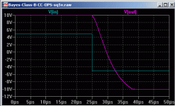
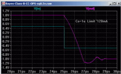
The second plot is with Co=1uF. This slews 2V in 2us then needs another 2us to recover from overshoot, a total of 4us. next are with 5V input (+/-10V swing).
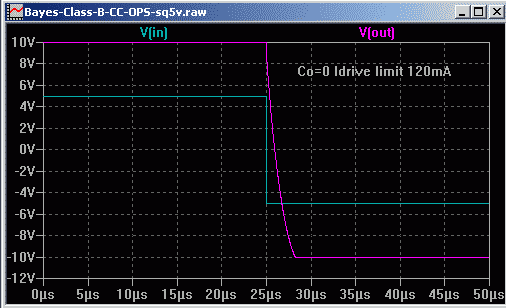

No Co slewing 20V takes 2us. With Co=1uF takes 13us.
To slew 20V with Co of 1uF you need I=C*dV/dt=1uF*20V/0.25us=80 amps. Assuming a beta of 50 the opamp needs to drive 1.6A which would require many LM7171's in parallel. But if Co could be reduced to say 100nF then its drive reduces to 160mA with one LM7171.
I found an ESR of 0.3 to 1 ohms in series helped to stabilize it. There may be other ways to get your amp stable with a lower Co without lowering the slew rate too much.
BTW most of the car IC power amps (eg TDA2003,4) used a 1 ohm in series with a 100nF output capacitor for stability and without this series resistor they would usually oscillate.
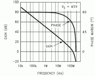
Re: My sims with Cp as a variable. Indeed Cp is fixed for the LM7171 see datasheet plot

.
The reason I made it a variable in my second sims here was to find out how much the opamps bandwidth (and slew-rate) affected the distortion. One simulation was with a pole at 3kHz and the other with no pole which is effectively an unlimited opamp bandwidth.
Surprisingly I found it didn't affect the weighted distortion by much which sounds counter intuitive. I assume the simulations are telling the truth (maybe someone can find a mistake). It also showed using ordinary THD was useless for this type of amp.
I hope that helps. Thanks for your appreciation.
Hi Steven,
Oh now I see why your other new thread is "Class-AB". You want to explore biasing options in that thread. So this one is for unbiased Class-B. Got it.
Your request for squarewave plots of Vin and Vout with and without 1uF output capacitors. Current limit is needed with a squarewave due to high slew rates.
It is difficult to model current limiting with a simple opamp macromodel. My model modulates Rout to give about 120mA limit based on current sense through a shunt resistor R2 of 300 ohms (20 times Rout) because LTspice doesn't like using I(Rout) in the Rout equation, but sensing current I(R2) at least allows it to run.
.
First plot is with 0.5V input (+/-1V output) with no Co. Slewing 2V in about 250ns. This is with the opamp pole of 30kHz. My earlier model was wrong by a factor of 10 - Oops).
The second plot is with Co=1uF. This slews 2V in 2us then needs another 2us to recover from overshoot, a total of 4us. next are with 5V input (+/-10V swing).
No Co slewing 20V takes 2us. With Co=1uF takes 13us.
To slew 20V with Co of 1uF you need I=C*dV/dt=1uF*20V/0.25us=80 amps. Assuming a beta of 50 the opamp needs to drive 1.6A which would require many LM7171's in parallel. But if Co could be reduced to say 100nF then its drive reduces to 160mA with one LM7171.
I found an ESR of 0.3 to 1 ohms in series helped to stabilize it. There may be other ways to get your amp stable with a lower Co without lowering the slew rate too much.
BTW most of the car IC power amps (eg TDA2003,4) used a 1 ohm in series with a 100nF output capacitor for stability and without this series resistor they would usually oscillate.
Re: My sims with Cp as a variable. Indeed Cp is fixed for the LM7171 see datasheet plot
.
The reason I made it a variable in my second sims here was to find out how much the opamps bandwidth (and slew-rate) affected the distortion. One simulation was with a pole at 3kHz and the other with no pole which is effectively an unlimited opamp bandwidth.
Surprisingly I found it didn't affect the weighted distortion by much which sounds counter intuitive. I assume the simulations are telling the truth (maybe someone can find a mistake). It also showed using ordinary THD was useless for this type of amp.
I hope that helps. Thanks for your appreciation.
Attachments
-
Bayes-Class-B-CC-OPS-sq5v.zip28.9 KB · Views: 90
-
 Bayes-Class-B-CC-OPS-sq5v-1uF.png4.4 KB · Views: 660
 -
 Bayes-Class-B-CC-OPS-sq5v-0uF.png4.2 KB · Views: 670
 -
 Bayes-Class-B-CC-OPS-sq0.5v-1uF.png4.6 KB · Views: 656
 -
 Bayes-Class-B-CC-OPS-sq0.5v-0uF.png4 KB · Views: 672
 -
 Bayes-Class-B-CC-OPS-sq.png9.5 KB · Views: 684
 -
 LM7171-Fig-13-gain-phase.png7.4 KB · Views: 659
You are amazing, thanks.
However, there is something interesting.
1. You should not have limited the current at 120mA, because, I am not sure whether the protection of LM7171 is so fast and, I hope, the amplifier can provide much higher current for a tiny period.
2. You should not have modeled poles of LM7171 with capacitors and resistors. I hope the emulation software ( Spice or whatever ) comprehensively covers LM7171.
Anyway, looks like the system can perform a jump for 250ns, although at low signal and without Co. LM7171 is fast at high signal and slow at low signal, but, I think, the speed limitation of your tests is caused by the inability of the system to provide high output currents to charge Co.
Yes, such a high value Co slows the system and requires high charging currents. This is why I have made another buffer ( which acts as a Darlington ), which will output a higher current.
Your previous tests used a slow climbing input voltage and, yes, the transient period was high, but, with such a slow input, the transient period is very tiny as compared to the half period of the slow input.
Co is, theoretically, NOT necessary. Co is not there to improve stability. Co is to eliminate the " machine gun noise ". Co is of very low ESR.
The lowest ESR capacitors are Ceramic, around 1uF. The lower ( or the higher ) the capacitance, the higher the ESR with most manufacturers. The only manufacturer who has the lowest ESR of 1.2mOhm with all values is Illinois Capacitor. Also, the higher the voltage, the lower the ESR. Illinois Capacitor makes Ceramic capacitors at high voltage, I think, something like 800V.
I am not sure what the reason for the " machine gun noise " is. May be oscillations, may be electromagnetic or electrostatic noise, may be internal transistor parameter changes with inputs, may be something else. The machine gun noise is present when the transistors are switched at high speed. The noise appears as bangs, a few per second, one per second, even, one every two or more seconds. Such is present with low power and fast signal transistors too.
An additional buffer, which acts as a Darlington, adds current to the charging current of Co, but, most importantly, increases the overall Beta and allows for a higher current. So does LM7171.
True, the additional buffer requires a higher jump over 2.8V as compared to 1.4V, but, this does not slow the circuit much and the increased Beta speeds the circuit more than the 2.8V jump slows the circuit.
At such a fantastic current as 80A, the Rcesat of all transistors increases and Beta decreases close to 1. Not known what the transient response is. Hope the transistors may be able to output high currents for a very tiny period.
Anyway, looks like the system is rather slow and an additional buffer may be of advantage. The most important is to reduce or eliminate Co. This, however, requires an oscilloscope. And Illinois Capacitor.
Japanese transistors are definitely an advantage as they are much faster than 2N3055 and MJ2955. Also, for +- 15V, so powerful transistors may not be necessary. The lower the power, the faster they are, yet, their Rcesat and Beta will be lower at a high currents.
Anyway, I am unable to do anything without a fast oscilloscope. I think, Spice and other programs may not be very accurate in this case.
I am afraid to exploit you more, but, in case you wish, you can run a 20kHz pure sine at the input with the two amplitudes you have used. Please, do NOT put any poles, capacitors, resistors at the output of LM7171. Leave Spice to decide.
LM7171 TI macromdel
Hi Steven,
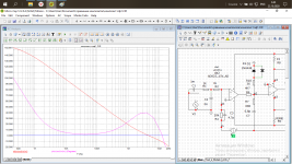
I have time for this. Using an utrafast opamp in an ancient common collector Class-B output stage has not been explored seriously to my knowledge. The pioneers of output stages did not have gains of 10,000 with unity gain rolloff at 200MHz with 140mA to use. So I think revisiting Class-B looks interesting, starting with the slower 2N3055/2955 to see what is needed to stop it oscillating.
The attached file uses the TI LM7171 macromodel. A jig is included for those who want to see its gain-phase plots. They are very close to the datasheet. Aol of 80dB and UGF 200MHz and Iout limiting 140mA.

Squarewave plot for Co=0 and Co=1u with 5V input below

This TI model slews about 50% faster, slightly higher UGF than my macromodel and slightly more output current. BTW the TI model current limit is hard limiting - it doesn't allow more than this for a short duration.
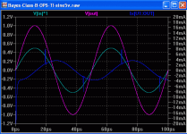
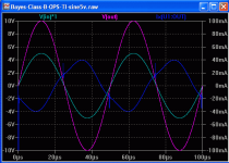
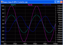
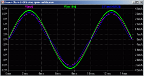
Next you wanted some sine plots at 20kHz at 5V and 0.5V inputs, 1st below is 5V with Co=1uF:

Next is 5V with 100nF

Then 0.5V with 1uF

Notice the jump/glitch (the opamp output current Blue) is shifted by the output capacitor; with 100nF the glitch is near the zero crossing but with 1uF it is before the zero crossing.(top plot).
What this confirms to me is that the crossover jump occurs so fast that the harmonics are well past the audio band (for 20kHz input), and even at 100Hz input much of the crossover harmonics are beyond 20kHz and therefore we won't hear much distortion with this Class-B amp.
The question is how to stop it oscillating and what causes the " machine gun noise "?
So now the TI model is working maybe others here might like to consider helping to understand and get this design stable.
I notice with the TI model and my model some Co is needed for the sinewave sims (like 100nF or 1uF) and some ESR is needed (like 0.3-1 ohms) to stop it oscillating at about 1MHz. Same old story, in a real bench circuit there are nH inductances in Co and opamp leads and transistor leads that are likely to make a real amp harder to get stable and optimise than the TI opamp and our BJT models suggest here.
Looks like we might have a new topology - Fast opamp-driven Class-B. Here's for hoping. Thanks Steven for putting the idea forward.
Hi Steven,
I have time for this. Using an utrafast opamp in an ancient common collector Class-B output stage has not been explored seriously to my knowledge. The pioneers of output stages did not have gains of 10,000 with unity gain rolloff at 200MHz with 140mA to use. So I think revisiting Class-B looks interesting, starting with the slower 2N3055/2955 to see what is needed to stop it oscillating.
The attached file uses the TI LM7171 macromodel. A jig is included for those who want to see its gain-phase plots. They are very close to the datasheet. Aol of 80dB and UGF 200MHz and Iout limiting 140mA.
Squarewave plot for Co=0 and Co=1u with 5V input below
This TI model slews about 50% faster, slightly higher UGF than my macromodel and slightly more output current. BTW the TI model current limit is hard limiting - it doesn't allow more than this for a short duration.
Next you wanted some sine plots at 20kHz at 5V and 0.5V inputs, 1st below is 5V with Co=1uF:
Next is 5V with 100nF
Then 0.5V with 1uF
Notice the jump/glitch (the opamp output current Blue) is shifted by the output capacitor; with 100nF the glitch is near the zero crossing but with 1uF it is before the zero crossing.(top plot).
What this confirms to me is that the crossover jump occurs so fast that the harmonics are well past the audio band (for 20kHz input), and even at 100Hz input much of the crossover harmonics are beyond 20kHz and therefore we won't hear much distortion with this Class-B amp.
The question is how to stop it oscillating and what causes the " machine gun noise "?
So now the TI model is working maybe others here might like to consider helping to understand and get this design stable.
I notice with the TI model and my model some Co is needed for the sinewave sims (like 100nF or 1uF) and some ESR is needed (like 0.3-1 ohms) to stop it oscillating at about 1MHz. Same old story, in a real bench circuit there are nH inductances in Co and opamp leads and transistor leads that are likely to make a real amp harder to get stable and optimise than the TI opamp and our BJT models suggest here.
Looks like we might have a new topology - Fast opamp-driven Class-B. Here's for hoping. Thanks Steven for putting the idea forward.
Attachments
-
Bayes-Class-B-OPS-TI-LM7171-sq.zip54.7 KB · Views: 78
-
 Bayes-Class-B-OPS-TI-sine500mV1u.png9.4 KB · Views: 618
 -
 Bayes-Class-B-OPS-TI-sine5v100n.png9.9 KB · Views: 621
 -
 Bayes-Class-B-OPS-TI-sine5v1u.png9.4 KB · Views: 606
 -
 Bayes-Class-B-OPS-TI-sq5v.png5.7 KB · Views: 611
 -
 Bayes-Class-B-OPS-TI-sq-cct.png10.8 KB · Views: 629
Thanks a lot. You are amazing as always.
Yes, I have exploited you a lot, so, please, do not press yourself to continue.
Anyway, first, I want to say I made a mistake in previous replies ( which I did not make in the document ) :
When the transient process is analysed with a large square wave input signal, only the period of jumping through 1.4V is of interest. As an example, when you apply +_ 5V and the output is +- 10V, the question is not how long the system takes to jump from - 10V to 10V, but, how long the system takes to jump a 1.4V region. This is because, when some voltage is applied at the input and this voltage changes from negative to positive and jumps over zero, the fast amplifier will jump the output from - 0.7V to 15V ( Vcc ) immediately ( as compared to the rest of the system ), or, very quickly. Thus, the transistors will have 15V on their bases very quickly and, then, interesting is mainly how long they take to jump to 0.7V. Once 0.7V is achieved, the system starts to work as an analogue system the same way as with always open transistors ( AB or whatever is called ).
Therefore, when +- 5V square wave input is applied and the output jumps from - 10V to 10V in 10us ( for example ), the jump over 1V takes < 10s / 20V approximately or 0.5us ( note the transient process is aperiodic and takes longer when the output voltage gets closer to the steady regime voltage of 10V in this example. In this example, the jump over 1.4V takes < 0.7us.
Also, not so huge current is necessary, yet, the bigger the current the better.
When a sine wave is applied two things happen : 1. Because the signal is slower when the input goes over zero, the output will become closer to the perfect one faster, i. e., the jump period does not create so much distortion. 2. The problem is, in such a case, the input signal difference on the two pins of the IC amplifier is very tiny when the slow input voltage goes over zero and is still near zero. The slew rate of LM7171 and some other amplifiers is much lower at tiny differences between the inputs.
Of course, whatever the result, a slowing system ( such as Co ) will always introduce non linearity error ( distortions ). The question is these not to be very high.
I am far from the dream this amplifier will be perfect and without any distortions and have never claimed this.
Of course, Co must not be equipped or the lowest possible value must be used.
And yes, in case anyone has an idea why I get the machine gun noise ( in a homemade system with wires all over the place ), I am most interested to know. I do not remember whether the machine gun noise appeared in a mono system, probably, yes, but, I do not remember.
Now, your new graphics with 20KHz pure sine input at various amplitudes : The input output graphics are so perfect, I want to, but, I am afraid even to dream this.
Now, in regards to Class B ( or whatever is called, i. e., voltage feedback amplifier with a push pull buffer ) with fast amplifier, yes, this is something interesting and, although of lower distortion quality to linear amplifiers, this may work to some extend, mainly when :
1. The IC amplifier is incredibly fast.
2. The output is unprotected or protected only by the RMS value of the output current and not by the amplitude ( or the amplitude protection is slow ).
3. The slew rate does not depend on the input pins difference or does not depend too much.
4. The fastest ( Japanese, Toshiba ) transistors are used for a given power and current. Note, the Beta and Rcesat ( Ucesat ) depend on the output current. Thus, the more powerful ( higher current ) the transistor is, the higher the Beta at a given high current and the lower the Rcesat ( Ucesat ). However, the higher the internal parasitic capacitances too, i. e., the slower the transistor. Thus, a nasty tradeoff can be used.
5. Obviously, the other audio parameters, such as low noise, best also be looked at.
6. I tried the circuit with UHF transistors, but, I decided against, because of their high Ucesat ( Rcesat ) at higher current. The only think I remember is the machine gun noise was present, but, also, then, I forgot to switch the modem off and I also got high frequency noise from the WiFi modem.
7. There are other fast amplifiers, LM7171 and LM6161 ( decompensated ) are not the only ones. Some of them have low noise. Some have even input difference guaranteed minimum slew rate ( I remember one from Texas instrument where the minimum slew rate was guaranteed to be 50V/us, whatever the inputs, there should be more ).
8. Look at New Japan Radio. New Japan Radio, or NJR, is a Japanese company which also makes wonderful amplifiers, such as their Muse series, which have a higher maximum power supply voltage than Texas Instruments ( Burr Brown ) and a higher maximum current. There are ultra fast amplifiers by New Japan Radio too. I do not know for sure, but, I am under the impression, people look at Texas Instruments, Analogue Devices, Phillips, etcetera and not very many people look at New Japan Radio. This is incredibly, totally, extremely, unbelievably wrong! Look at New Japan Radio first and, then, look at the others to compare.
9. The same applies to Toshiba, Panasonic and the other Japanese transistor makers. Basically, Japan First!
10. The same applies to capacitors : TDK for ceramics, Nichicon for electrolytics. Exception : the nor so well known Illinois Capacitor for lowest ESR Caramics and the lowest ESR in general. May be 800V, may be big, but, 1.2mOhm ESR says everything there is to say ( I think their ESL is also the lowest or low ).
One thing for sure : I can guarantee such a Class B, or whatever is called, amplifier will work. This is for sure. The question is not whether, but, how. What is the quality?
Thus, I think I can say for sure, those who want an inexpensive amplifier can use this idea. The amplifier does sound excellently and will sound even better with better transistors. However, I cannot guarantee the quality. Yet.
As far as the quality is concerned, I can say, the documentation of LM7171 says the noise is 100nV / ( SQRT( Hz ) ). This is much higher than 1nV / ( SQRT( Hz ) ), which Texas Instruments ( Burr Broun ) claim for one of their newest bipolar audio amplifier and the comparable Muse counterparts.
However, there are low noise fast amplifiers, some of them with a slew rate of 700V/us and, to be honest, I cannot here much noise out of the amplifier even with the lousy wiring. The number 100nV / ( SQRT( Hz ) ) is some kind of an extreme, probably, at very high temperature and other extremes.
Again, I do not claim and have never claimed Class B, or whatever called, would be better than the linear amplifiers.
Now, there is another dirty competitor : Class D. Who would want a Class B, when they can make a Class D? Class D has the lowest losses ( with GaN transistors ). Class B has higher losses, because, the Uce and Uec of each transistor goes analogously from 0 to nearly Vcc and so does Ice and Iec. Thus, the transistors do consume power. In class D, however, the transistors are either fully open or fully closed and, theoretically, consume zero power, practically, almost nothing.
The simplicity and reliability of Class B or whatever called is another advantage, though.
LM7171 Class-B noise sims
Hi Steven,
What effect does the opamps internal noise have on the jump region? The attached file has noise added.
The LM7171 is 14uV/RtHz (input referred) above the corner frequency of 10kHz and below 10kHz it rises as Sqrt(freq). Below 10kHz it is pink noise and above 10kHz it is white noise. I use recorded pink noise added to the opamp input and LTspice White(t) function for white noise flat up to 1MHz (just high enough to modulate the jump region bt not too high to slow simulations too much).

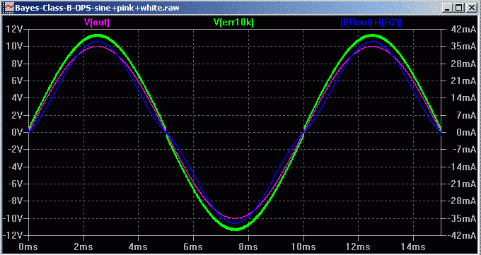


Some opamp noise does not do any harm, it may actually help. BTW the feedback around the opamp reduces the internal noise within the audio bandwidth.
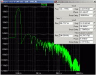
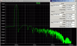
The above FFT plots shows noise in the 1kHz-10kHz region (where our hearing is most sensitive) is about 10dB below the highest distortion harmonic, the 3rd at -72dB with 10Vpk out and -50dB with 1Vpk out. The 3rd harmonic is not audible and the noise in the 1kHz-10kHz region is not much of a concern with most speakers (like 90dB/w/m or less)..
The 3rd harmonic is most likely from LSD (Large Signal Distortion) due to beta fall in the power transistors. The crossover distortion occurs over 1-2us every zero cross, so must have harmonics way above the 3rd, probably significant levels start above the audio band. (To clearly see crossover distortion harmonics look at the 'err10k' signal FFT - it shows the error magnified by 80dB).
I'm not sure if I got the noise levels correct for the LM7171 - just ball-park settings so far. Maybe some opamp experts can get a closer fit to the datasheet. In the mean-time this simulation gives some idea of opamp noise in this type of Class-B amp and how to perform a transient (time domain) simulation with noise.
Simulations were quite slow with a 1MHz white noise source - taking 15 minutes to do just 3 cycles of 100Hz. That's why I use my simpler LM7171 model since the TI model is slower and takes 10 times longer to run.
BTW my circuit includes record outputs (if you enable them) to compare the undistorted input (but with pink noise) and the amp output to find out if you can hear any of the crossover distortion.
Hi Steven,
What effect does the opamps internal noise have on the jump region? The attached file has noise added.
The LM7171 is 14uV/RtHz (input referred) above the corner frequency of 10kHz and below 10kHz it rises as Sqrt(freq). Below 10kHz it is pink noise and above 10kHz it is white noise. I use recorded pink noise added to the opamp input and LTspice White(t) function for white noise flat up to 1MHz (just high enough to modulate the jump region bt not too high to slow simulations too much).
Some opamp noise does not do any harm, it may actually help. BTW the feedback around the opamp reduces the internal noise within the audio bandwidth.
The above FFT plots shows noise in the 1kHz-10kHz region (where our hearing is most sensitive) is about 10dB below the highest distortion harmonic, the 3rd at -72dB with 10Vpk out and -50dB with 1Vpk out. The 3rd harmonic is not audible and the noise in the 1kHz-10kHz region is not much of a concern with most speakers (like 90dB/w/m or less)..
The 3rd harmonic is most likely from LSD (Large Signal Distortion) due to beta fall in the power transistors. The crossover distortion occurs over 1-2us every zero cross, so must have harmonics way above the 3rd, probably significant levels start above the audio band. (To clearly see crossover distortion harmonics look at the 'err10k' signal FFT - it shows the error magnified by 80dB).
I'm not sure if I got the noise levels correct for the LM7171 - just ball-park settings so far. Maybe some opamp experts can get a closer fit to the datasheet. In the mean-time this simulation gives some idea of opamp noise in this type of Class-B amp and how to perform a transient (time domain) simulation with noise.
Simulations were quite slow with a 1MHz white noise source - taking 15 minutes to do just 3 cycles of 100Hz. That's why I use my simpler LM7171 model since the TI model is slower and takes 10 times longer to run.
BTW my circuit includes record outputs (if you enable them) to compare the undistorted input (but with pink noise) and the amp output to find out if you can hear any of the crossover distortion.
Attachments
-
Bayes-Class-B-OPS-sine+pink+white.zip258.4 KB · Views: 77
-
 Bayes-Class-B-OPS-500mVsine+pink+white-FFT-100n.png13 KB · Views: 539
 -
 Bayes-Class-B-OPS-5Vsine+pink+white-FFT-100n.png13.1 KB · Views: 553
 -
 Bayes-Class-B-OPS-5Vsine+pink+white-jump-100n.png13.3 KB · Views: 549
 -
 Bayes-Class-B-OPS-5Vsine+pink+white-100n-time.png10 KB · Views: 554
 -
 Bayes-Class-B-OPS-5Vsine+pink+white-cct.png16.9 KB · Views: 565
Thank you. Excellent as usually.
Although noise is important and does have some impact over the zero crossing, I am not so much concerned with the noise, except for the machine gun noise, which, when present, makes the sound unbearable.
I, also, forgot to mention I do not have the necessary power supply and use a +- 15V, 2x5W power supply, as well as +- 9V and +- 5V, all 2x5W too. All these are regulated outputs. +- 15V, 2x5W, non regulated is also available as well as a non regulated +- 15V, 10A/h battery power supply.
All these are linear power supplies.
I, also, have a +- 15V, 2x5W, switching power supply at 10KHz, which, I have not yet tried.
More powerful, linear, regulated power supply is a good idea.
In regards to the fast amplifier and noise : Usually, the higher the slew rate, the higher the noise, yet, there are some high slew rate, low noise amplifiers. Decompensated amplifiers are OK, as the preamplifier can be used for volume adjustments. Decompensated amplifiers are faster, yet, their speed may decrease because of the feedback. LM7171 is also decompensated but only to a gain of 2. LM6161 is, probably, the same as LM7171, but, decompensated to a higher gain. Again, there are more amplifiers with a high slew rate and lower noise.
During the zero crossing, the amplifier is supposed to go to saturation and must be latch free, which, most of them are. However, when the amplifier goes into saturation, the noise may be slightly higher, yet, I am not concerned with this minute problem now. The effect should not be significant.
The reason I mentioned the noise was, because, people in audio, a. k. a. audiophiles, are extremely concerned with this.
Anyway, you or anyway interested in the topic, who has a good power supply can make a similar mono amplifier with an inexpensive amplifier IC and a couple of transistors ( or 4 transistors for a dual, Darlington like, buffer ). Preamplifier is good to have and, ideally, mounted on the same PCB, although an external one may be possible to be used. Another quad amplifier can be used for the preamplifier and filters. Add some power supply capacitors and, voila, there is an amplifier. TIP transistors or any transistors can be used.
Interesting is to see what an oscilloscope would say, although, you have carried out an excellent and outstanding work, for which, I thank you very much.
I think, the Texas Instruments Spice description should be more accurate.
Again, thank you very much and, please, think of a possibility for you to make an amplifier. The best is, probably, to start with a mono amplifier not to have any electromagnetic influence from channel to channel.
Do not put Co initially, but, leave some room on the PCB for a few capacitors in parallel, to have options in case these are necessary.
You do not need to use the same LM7171 amplifier nor the same transistors.
You can do it differently.
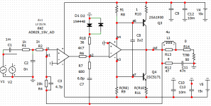
Opamp and transistors operate on a common load.When the transistors are closed, the signal comes from the output of the operational amplifier.
Distortion is reduced
Opamp and transistors operate on a common load.When the transistors are closed, the signal comes from the output of the operational amplifier.
Distortion is reduced
Attachments
Last edited:
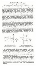
@stanislav1957 This method you are talking about would deserve much more attention. The following page is from a german book: U. Tietze Ch. Schenk: Halbleiter - Schaltungstechnik (Springer-Verlag 1999) . It seems to be this is one of the most effective ways to achieve realistic sound. The Hungarian-based Gauss Audio is developing their amplifiers based on this method. As far as I know, they have developed similar but a more effective solution to decrease crossover and impulse distortions, than described in book I mentioned.
Attachments
- Home
- Amplifiers
- Solid State
- Amplifier