Hi mjona,
That was their test parameters. The reduction in THD holds for lower powers and is before adding feedback - so valid for a Stassis type amplifier of any other design that excludes the output section from the feedback loop. When you add feedback, there is still a great reduction in distortion since the diff pair has less correction to do. The amount of reduction depends upon how far the outputs were from being matched to begin with. The important thing I'm trying to get across to people is that matching matters and isn't an expensive way to reduce distortion in their builds. Transistors that didn't match can be used in other projects - so minimal loss there.
Matching the like transistors for each polarity also reduces distortion in that it allows them to operate as one and remain under control of the circuit. Having a random and soft transition from not conducting to conducting isn't going to help having a smooth changeover from the PNP half to the NPN half.
Hi Chamberman,
While I can't dispute your numbers, and will not attempt to do that, I think that uniformity across the wafer may not hold true for the larger geometry in discrete parts like transistors. Especially power transistors. The one time I did see uniformity like that (On Semi MJW0281 / MJW0302), the devices were discontinued. That was a very sad event for me. Common were beta figures in the 100 range varying only a few counts. Flyers were maybe 4 counts off average. Those parts were a dream come true for me. I was prepared to pay more for those parts had they remained in production.
With normal output transistors I see these days, the beta counts are much more random and matching is still beneficial. I would love a day where I didn't have to match parts! The signal transistors have also improved a great deal, but the variance is still too great to just pluck them out of a bag or drawer and use them in pairs. Better than in the 70's for sure, but we aren't there yet. Beta variations are much greater with signal transistors than the power types. I wonder if that is simply due to the fact that we are dealing with higher transconductance devices, or just the smaller die size? You would have the experience to shed some light on that issue.
- Chris
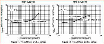
Speaking of transconductance, Figures 11 and 12 in the datasheets for MJL21193 and MJL21194 show there are parts of the line below 1A where the plot is reasonably flat. Perhaps some use of this could be to devise a common emitter amplifier test jig.
Attachments
We have bigger problem's MJL3281/1302 are on a long back order, coming down to one main guy making bjts for audio amps.
Just use NJW0xxx, they are is stock at Mouser. I used many of them, without any problem, even with +/-85V rails.
Now I changed to 2SC6145/2SA2223...
Sajti
Hi Rick,
I know this was debated elsewhere, but I am reasonably sure that matching VBE is pointless. There isn't enough variation in that parameter to begin with, and it doesn't vary strongly with temperature. You are pretty much guaranteed to have close matches using emitter - base voltage.
Beta, on the other hand, varies strongly with temperature and is highly variable as a parameter. If you match the beta, chances are extremely high your VBE is going to match anyway. Again with the direct observations, a mismatched pair (beta) varies more with temperature (in DC offset at the amplifier output) and does result in higher static DC offset. Distortion performance also varies with beta match. I think Bob Cordell and Douglas Self would both support me on that.
-Chris
hi Chris, I usually use hfe matching for ltp and that makes the dc offset low. I think matching hfe is enough because I think the measuring instrument uses the same vbe to calculate hfe
Hi greenocean,
The matcher normally doesn't consider Vbe at all. They generally work on current ratios. That voltage drop is probably within a few mV between matched transistors anyway. That parameter simply does not affect the beta as it has a very small range of values compared to the value of beta which varies quite a lot between transistors. I have found that the values of vbe between beta matched transistors to be close to each other.
-Chris
Matching Vbe or Hfe
It all depends of the matcher circuit and / or matching procedure.
In a balanced circuit, both are important, but depending of the actual circuit, one or the other is dominant, more or less.
I think, there is no dogma like hfe matching is better or Vbe matching is better.
I have presently a case where I must match in the actual circuit, to take care of both Vbe and Hfe. So, I do not care wether I match Vbe or Hfe, I match transistors in the circuit they will be used. The drawback is, they match for a specific circuit, a circuit I am not allowed to change.
So, I am very interested to read here, that transistors matching in one ( Vbe or Hfe), do match in the other ( Hfe or Vbe). If true, this, makes things simple.
Vbe Tempco is usually given as -2 mV / °C or -2.2mV / °C
Hfe Tempco is +0.6% / °C for 2N2222 ( from http://qucs.sourceforge.net/docs/tutorial/bjtbias.pdf )
Hi mchambin,
It's not a dogma at all. Just the result of many years of observation working with these parts. Too bad my 2N2222A transistors can't read your article. It would make them more stable, because Hfe changes more than the figure you specified.
If you match Hfe, the match holds in any circuit I have tried. The vbe will naturally match as we now have parts that are more similar to each other. That and vbe doesn't change very much compared to hfe.
It's interesting that you match transconductance with tubes. I just got finished measuring 21 KT-88 tubes (4 were 6550A actually). With just about any technology you want to use, matching components can increase circuit performance in areas where you can make use of matched parts. Transistors (BJT's) are no different. But it's beta that matters, not the vbe drop of the B-E diode that we have as a consequence of how the BJT is made.
-Chris
Well, please take two 2N2222 or wathever you like similar, two 4.7K resistors, one 7K resistor.
Wire a LTP. Emiters together at the 7K to -15V, Both bases at 0V, Collectors at the 4.7 K to +15V
Put your meter to measure voltage between collectors.
Ready ?
Now you read some non zero voltage. Why ? What is the reason for the mismatch ?
Now, hold one or the other transistor? What is the reason for the mismatch changing ?
More fun, now. Lift the two bases from the 0V, then insert 22K resistors to connect bases to 0V.
Play again. Now, what does the mismatch come from ?
You just described the matching jig I use. The values are different but you have the concept down. I used 0.1% resistors for both base land collector resistors.
With the jig, it is critical to keep the transistors in thermal contact, isolated from air currents using a foam hood for the pair, and a box for air currents. You can even watch the offset bounce as it equalizes if you use a low tail current. The same thing happens with higher tail currents, but it doesn't take as long for them to reach a thermal balance.
If you breathe on one, or touch it with your finger, that transistor conducts more. This is the same reason you can't easily match beta values using a meter with the beta function. The transistor dies must be at the same temperature for these measurements to be valid. I can also measure base currents and have played with this.
So mchambin, have you built one of these jigs yet? It sounds like you might find it very useful. I do know it will allow you to match transistors <1%.
-Chris")
With the jig, it is critical to keep the transistors in thermal contact, isolated from air currents using a foam hood for the pair, and a box for air currents. You can even watch the offset bounce as it equalizes if you use a low tail current. The same thing happens with higher tail currents, but it doesn't take as long for them to reach a thermal balance.
If you breathe on one, or touch it with your finger, that transistor conducts more. This is the same reason you can't easily match beta values using a meter with the beta function. The transistor dies must be at the same temperature for these measurements to be valid. I can also measure base currents and have played with this.
So mchambin, have you built one of these jigs yet? It sounds like you might find it very useful. I do know it will allow you to match transistors <1%.
-Chris
I forgot to answer this. I did in 1966.So mchambin, have you built one of these jigs yet?
CCS tail current?
Committed to PCB, or perf board?
Still use it?
I gave my design to the members here and there are at least three PCBs designed for it. My original was built on perf board as I needed a close match, then I added the PNP section and finally designed a PCB once the perf board project was getting a little tattered. I've since had three PCB designs on my own. THose members that designed their own PCB did a very good job. You can source a PCB and build a modern version. The CCS has a thermally connected LED Vref, so it's more stable as well. You might want to look into one.
I did discover that the PCB headers from China don't work well. Buy them from a US source (or any authorized distributor for a name-brand product). I managed to find some 6 pin DIP sockets that work, but a normal 8 pin allows all pinouts to be used. So use the 8 pin types. You can figure out a pinout that uses 4 pins to allow all the pinouts used with signal transistors. I used 10K base resistors to get into the ball park for real world circuits, and 100R0 0.1% resistors for the collector loads. You have a meter between the collectors as a null detector. I also use a centre tune meter for this.
The reason for DC drift is mostly Hfe. The temperature can't help but also drop the Vbe as well. In reality, Vbe doesn't change that much compared to Hfe.
-Chris
The reason for DC drift is mostly Hfe. The temperature can't help but also drop the Vbe as well. In reality, Vbe doesn't change that much compared to Hfe.
-Chris
I find this comment hilarious.


The question wasnt about drift, it was about mismatch. In ltp its all about Vbe. The pairs operating point is determined by the diferential voltage, zero difference should give equal currents, unmatched Vbe will unmatch currents. Yes Vbe dosnt change much, but a small change means a large current change means a large mismatch, so sometimes its the more important parameter. This makes measuring Vbe changes harder than Ic changes, it dose not mean Vbe matching is less important.The reason for DC drift is mostly Hfe. The temperature can't help but also drop the Vbe as well. In reality, Vbe doesn't change that much compared to Hfe.
-Chris
Now thinking out loud: in parrallel output tranies the zero out bias currents are set by a Vbe multiplier ( voltage ) so all the bases ( usually tied together) have the same voltage. This implies that the bias current differences of each trany depends on Vbe mismatch ( and Re mismatch). Now we extend this to operation, where again the bases all have the same voltage, ( in most amps the OPS is voltage driven) , does this not imply Vbe mismatch is the important parameter?
Since Vbe and Ic are related, matching one will match the other. matching beta may be more accurate but if your meter shows any Vbe difference between transistors you can match them, closest ones together. A lot easiesr than a jig. And Temprature has less effect. The only time I would not trust Vbe meter matching is on power transitors, which should be measured with higher Ic than a Vbe meter uses. You can still match Vbe's but you need a jig to drive Ic.
Maybe Chris should focus on repairs vs semiconductor physics
I really do not know the usefulness of trying/attempting to match "npn" & "pnp" complementary pairs. Say for example a manufacturer of amplifiers vs a tech doing a repair or mod.
Knowing the small lot to lot and within lot variations these days with better processing, will you ever find any matches and how much stock must you go through to find a match? How close is close enough to say it is a match?
I think Chris is missing the point about feasibility in npn/pnp matching and the simple method of measuring Vbe for a dual. In all practical purposes for audio, forget about measuring hfe or other device parameters, unless your are running a QA dept.
I have not seen a proof or statistics about this.Since Vbe and Ic are related, matching one will match the other.
I wish this is true, it makes transistor matching much simpler.
Is there a reliable source about this ?
Matching at low Ic ( less or equal 1mA ) makes thinks easier, quicker because it is not troubled by self heating. Here it is expected they keep matched at higher Ic.
I think this holds true for low power transistors as used in an amplifier front stage.
I think it is wrong for output stage power transistors made for hight Ic.
All that matching jazz about the transistors at the front stage LTP would stop if diyers were using opamps instead of re inventing them.
Matching of the front end LTP in op amps is well cared of. How well they match is precisely documented in the specifications.
Have a look to an op-amp data sheet. For a bipolar input op-amp.
Vos relates to Vbe matching
Ios relates to Hfe matching.
Depending of the application one or the other or both are important. In most cases Vos is the one that matters.
- Status
- This old topic is closed. If you want to reopen this topic, contact a moderator using the "Report Post" button.
- Home
- Amplifiers
- Solid State
- Matched output transistors: does gain change with age?