The voltage between these two points should increase as you you alter the trimmer.
If it does then note the minimum and maximum voltages you see and report back. You need to be seeing around 3.5 volt before any increase in bias current will be apparent. Assuming this alters OK you should then turn the preset back to give minimum voltage across the cap.
If it does then note the minimum and maximum voltages you see and report back. You need to be seeing around 3.5 volt before any increase in bias current will be apparent. Assuming this alters OK you should then turn the preset back to give minimum voltage across the cap.
Attachments
A bit more for you to be going on with because I'll have to leave it for today...
If the DC is offset is close to zero (no DC at the speaker terminals) then you can carefully test the amp with a speaker and music as it stands now.
Whilst the bulb is in circuit I would connect the speaker after first having turned the amp on. Only play it very quietly (the bulb will flicker and light) because otherwise the rails will collapse as the bulb limits current. If that is OK then disconnect the speaker and switch off.
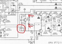
If the 'voltage across the cap' test was OK and the voltage altered as it should then it means we need to very slightly increase the available voltage in the bias generator to get the output transistors to conduct and we do this by reducing the value of R754 (4k7) a little, say to the next value down such as 3k9.
That will allow the trimmer to take the bias voltage that bit higher.
If you try this then have NO speaker connected and always use the bulb. And remember to have the preset turned to give MINIMUM voltage across the cap initially.
(it can be confusing because minimum voltage across the cap will correspond to maximum resistance of the trimmer)
Good luck, take it slow and I'll look in tomorrow")
If the DC is offset is close to zero (no DC at the speaker terminals) then you can carefully test the amp with a speaker and music as it stands now.
Whilst the bulb is in circuit I would connect the speaker after first having turned the amp on. Only play it very quietly (the bulb will flicker and light) because otherwise the rails will collapse as the bulb limits current. If that is OK then disconnect the speaker and switch off.
If the 'voltage across the cap' test was OK and the voltage altered as it should then it means we need to very slightly increase the available voltage in the bias generator to get the output transistors to conduct and we do this by reducing the value of R754 (4k7) a little, say to the next value down such as 3k9.
That will allow the trimmer to take the bias voltage that bit higher.
If you try this then have NO speaker connected and always use the bulb. And remember to have the preset turned to give MINIMUM voltage across the cap initially.
(it can be confusing because minimum voltage across the cap will correspond to maximum resistance of the trimmer)
Good luck, take it slow and I'll look in tomorrow
You're not doing anything wrong. You should be see a tiny increase in voltage across the resistors plus the lamp should glow a little brighter. The 3 mv you see equals 15 milliamps flowing in the 0.1 ohm resistors. About right.
What you need to do is to check that the voltage across C752 increases as you turn the trimmer.
Up to now all sounds OKand the lack of bias may just be down to slight differences in the semiconductors used... which we can easily fix
I take it the - and +22mv you read are as measured from ground. If so then that's really good as well because that means the DC offset is near zero.
The last post should of read:
"voltage readings on either of the outer pins read -22.60mV (MAX) or -22.54mV(MIN)".
If you have -22mv or +22mv on either end of that dual 0.1 resistor (as measured from ground) then that's fine. That's just a DC offset. That reads as though you are measuring from a ground reference for that.
If you are seeing -22mv or +22mv across the resistor (measured between the two ends) then that is to high and in any case should change with the trimmer.
Read through my last couple of posts again and see if it comes together a bit better
If you are seeing -22mv or +22mv across the resistor (measured between the two ends) then that is to high and in any case should change with the trimmer.
Read through my last couple of posts again and see if it comes together a bit better
You're not doing anything wrong. You should be see a tiny increase in voltage across the resistors plus the lamp should glow a little brighter. The 3 mv you see equals 15 milliamps flowing in the 0.1 ohm resistors. About right.
What you need to do is to check that the voltage across C752 increases as you turn the trimmer.
Up to now all sounds OK
I take it the - and +22mv you read are as measured from ground. If so then that's really good as well because that means the DC offset is near zero.
The voltage on the NEG lead of C752 varies from ~4.3V to ~5V when the trimmer R766 is adjusted from MIN to MAX resistance.
If you have -22mv or +22mv on either end of that dual 0.1 resistor (as measured from ground) then that's fine. That's just a DC offset. That reads as though you are measuring from a ground reference for that.
If you are seeing -22mv or +22mv across the resistor (measured between the two ends) then that is to high and in any case should change with the trimmer.
Read through my last couple of posts again and see if it comes together a bit better
I took voltage readings from a ground reference. The readings on either of the outer pins read -22.60mV at MAX resistance and -22.54mV at MIN resistance; thats a difference of only 0.06mV between MIN and MAX.
Should the voltage measurements on either of the two outer pins of the cement resistor, be the same or very similar?
The voltage difference on R766 seems to be much lower than the difference on R767, is that normal?
In response to : Marantz PM66KI amp - resistor keeps dying!
The voltage on the NEG lead of C752 varies from ~4.3V to ~5V when the trimmer R766 is adjusted from MIN to MAX resistance.
The voltage on the NEG lead of C752 varies from ~4.3V to ~5V when the trimmer R766 is adjusted from MIN to MAX resistance.
Its the voltage across the cap we are after. Put your meter negative lead on the negative end of the cap, and the meter positive lead on the positive end of the cap.
What is the range of voltage you see?
I took voltage readings from a ground reference. The readings on either of the outer pins read -22.60mV at MAX resistance and -22.54mV at MIN resistance; thats a difference of only 0.06mV between MIN and MAX.
Ground referenced means you are effectively measuring the DC offset at the output. All good there.
Should the voltage measurements on either of the two outer pins of the cement resistor, be the same or very similar?
If ground referenced for the measurement then very similar, but not exactly the same. How similar depends on the current flowing.
All looks good here up to now. The middle pin of the resistors should actually be even closer to zero.
The voltage difference on R766 seems to be much lower than the difference on R767, is that normal?
In response to : Marantz PM66KI amp - resistor keeps dying!
This will depend on the bias conditions to some extent. With no bias current flowing there will be essentially no voltage across this resistor. So that's not a problem at this stage.
(Just testing the amp with a speaker at this stage would be useful. If lack of bias is the only issue then the amp should actually work OK audibly)
I'm hoping the only thing we need to do is tweak that resistor as I mentioned yesterday, but before we do that we need to 'prove' that everything else is OK.
Its the voltage across the cap we are after. Put your meter negative lead on the negative end of the cap, and the meter positive lead on the positive end of the cap.
What is the range of voltage you see?
The range of voltage is: ~3.34V (MAX resistance of R766) to ~4.05V (MIN).
Ground referenced means you are effectively measuring the DC offset at the output. All good there.
If ground referenced for the measurement then very similar, but not exactly the same. How similar depends on the current flowing.
All looks good here up to now. The middle pin of the resistors should actually be even closer to zero.
This will depend on the bias conditions to some extent. With no bias current flowing there will be essentially no voltage across this resistor. So that's not a problem at this stage.
(Just testing the amp with a speaker at this stage would be useful. If lack of bias is the only issue then the amp should actually work OK audibly)
I'm hoping the only thing we need to do is tweak that resistor as I mentioned yesterday, but before we do that we need to 'prove' that everything else is OK.
The range of voltage is: ~3.34V (MAX resistance of R766) to ~4.05V (MIN).
That sounds reasonable.
So 4.05V available has to be able to bias all six of the transistor junctions in the output stage. That works out at 0.675V as an average per device... right on the edge of 'will it or won't it conduct'.
I suspect the different transistors used have slightly different forward voltages caused by modern and different manufacturing processes. What we need to do is to get that 4.05V a fraction higher and we can do that by making R754 a little lower in value.
I would suggest trying a 3k9 in place of the 4k7 fitted.
Be sure to set the preset back to the setting that gives lowest voltage across the cap before switching the amp on (so max resistance of the preset).
One other thought... and its important. It is possible that the lower rails you will be getting with the bulb in place might be contributing to the low bias state.
You could as a test try the amp on full mains and see if the bias adjusts OK. If it doesn't then we go back to the bulb and you swap the resistor.
Hi
I have removed the series lamp limiter out of circuit and retested R768 (0.1x2 resistor) and I am getting -22mV from MAX to MIN resistance (adjusting R756).
Also the voltage range of C752 is: ~4.984V (MAX resistance of R756) to ~4.264V (MIN).
I think I will order some 3k9 resistors.
Thanks
I'm never sure whether you are talking of DC offset or bias currents (voltage across the 0.1 ohms).
-22mv as an offset is fine and offset is not related to bias current adjustment. Offset is the voltage you measure across the speaker terminals.
-22mv measured across the two 0.1 ohms would equal 110 milliamps which is already on the high side. That would not need any alteration to components.
Have you actually tried the amp on a speaker yet?
I'm never sure whether you are talking of DC offset or bias currents (voltage across the 0.1 ohms).
-22mv as an offset is fine and offset is not related to bias current adjustment. Offset is the voltage you measure across the speaker terminals.
-22mv measured across the two 0.1 ohms would equal 110 milliamps which is already on the high side. That would not need any alteration to components.
When measuring voltage on R768 (0.1x2 resistor), I put the positive probe on one of end pins of the resistor and the negative/black probe on on of the (pcb) heatsink ground points. At the moment i am using two multimeters to measure the voltage on both end pins of R768 at the same time. I put the positive lead of multimeter A on one of the end pins of R768 and the positive lead of multimeter B on the other end pin of R768; then the negative/black probes of each meter is placed on one of the (pcb) heatsink ground points.
-22mV is what I am measuring on one of the end pins of the resistor R768. Both of end pins measure the same.
Also when I adjust R756 trimmer, the voltage on either of the end pins of R768 doesn't change.
I have tested the voltages with and without the series lamp limiter limiting the current.
Hope this answers the above question(s).
Have you actually tried the amp on a speaker yet?
Not yet.
Thanks
That explains what you doing
So... all you are doing with the two meters is really measuring DC offset.
The trimmer doesn't adjust offset (although in practice it might appear to change it a little) but we are not really interested in that.
What you need to do is use just one meter and connect one lead to one outer end of the resistor network and the other lead to the other end of the network.
Doing that means you are measuring directly across what is effectively a 0.2 ohm resistor.
The voltage you see here will enable you to calculate the current. The manual suggests a rather precise figure of 38.9 milliamps which means you would see just 7.78 millivolts across those combined series resistors (or 3.89 millivolts across each).
You will never get the bias current set that accurately as it drifts naturally with temperature. Aim for no more than 10 millivolts across the pair (which would be 50 milliamps) as a maximum. Lower is fine.
Does that make sense?
That explains what you doing
So... all you are doing with the two meters is really measuring DC offset.
The trimmer doesn't adjust offset (although in practice it might appear to change it a little) but we are not really interested in that.
What you need to do is use just one meter and connect one lead to one outer end of the resistor network and the other lead to the other end of the network.
Doing that means you are measuring directly across what is effectively a 0.2 ohm resistor.
The voltage you see here will enable you to calculate the current. The manual suggests a rather precise figure of 38.9 milliamps which means you would see just 7.78 millivolts across those combined series resistors (or 3.89 millivolts across each).
You will never get the bias current set that accurately as it drifts naturally with temperature. Aim for no more than 10 millivolts across the pair (which would be 50 milliamps) as a maximum. Lower is fine.
Does that make sense?
Yes that makes sense. I will retest tomorrow and report back.
Thanks for the clarification.
OK
And remember no speakers attached for setting bias current.
Try it with the bulb first so that you know what to expect... these are very tiny voltages and you might feel happier soldering wires to the test points and bringing those out to the meter, then you can concentrate on the readings and turning the trimmer.
One slip of the probes would be a disaster.
A nice set of test lead ends is useful to have, like this: K-arm Multimeters Test Leads - Threaded Extension Hook Probe Testing Clip 4mm Aperture - - Amazon.com
That explains what you doing
So... all you are doing with the two meters is really measuring DC offset.
The trimmer doesn't adjust offset (although in practice it might appear to change it a little) but we are not really interested in that.
What you need to do is use just one meter and connect one lead to one outer end of the resistor network and the other lead to the other end of the network.
Doing that means you are measuring directly across what is effectively a 0.2 ohm resistor.
The voltage you see here will enable you to calculate the current. The manual suggests a rather precise figure of 38.9 milliamps which means you would see just 7.78 millivolts across those combined series resistors (or 3.89 millivolts across each).
You will never get the bias current set that accurately as it drifts naturally with temperature. Aim for no more than 10 millivolts across the pair (which would be 50 milliamps) as a maximum. Lower is fine.
Does that make sense?
Here are my results:
With the series lamp limiter on:
Left channel
R767 = 6.79mV across the resistor
Right channel
R768 = 0mV & no change when R766 trimmer is adjusted from MAX to MIN resistance.
With the series lamp limiter off:
Left channel
R767 = ~10.97mV across the resistor
Right channel
R768 = 0mV & no change when R766 trimmer is adjusted from MAX to MIN resistance.
FYI:
no speakers are connected during the above tests. Its the RIGHT channel that we are working on.
Here are my results:
Right channel
R768 = 0mV & no change when R766 trimmer is adjusted from MAX to MIN resistance.
Right channel
R768 = 0mV & no change when R766 trimmer is adjusted from MAX to MIN resistance.
FYI:
no speakers are connected during the above tests. Its the RIGHT channel that we are working on.
So it looks like your Vbe stage has a fault somewhere.
Maybe Vbe transistor gone short.
Maybe fault in constant current source or VAS.
Start by checking al those components in situ.
So we are back to post #69, that the available bias voltage is possibly marginally low for the modern semiconductor replacements.
Follow post #69 and swap the resistor mentioned. Use the bulb at all times for this.
I have swapped R752 for a 3.9K and here are my results:
R768 = 0 V across the resistor and no change wheen R766 is adjusted from MAX to MIN resistance.
C752 = 4.756 V to 3.731 V (when R766 is adjusted from MAX to Min resistance).
FYI:
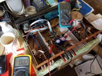
I have attached photo showing how i'm testing both R768 and R767.
Attachments
- Status
- This old topic is closed. If you want to reopen this topic, contact a moderator using the "Report Post" button.
- Home
- Amplifiers
- Solid State
- Marantz PM66KI amp - resistor keeps dying!